A radio frequency front-end circuit and a mobile terminal

A radio frequency front-end and radio frequency circuit technology, applied in the field of terminal applications, can solve the problems of high path loss and long wiring, and achieve the effects of reducing path loss, simple circuit design, and shortening radio frequency layout and wiring

Active Publication Date: 2019-06-07
VIVO MOBILE COMM CO LTD
View PDF4 Cites 19 Cited by
  • Summary
  • Abstract
  • Description
  • Claims
  • Application Information

AI Technical Summary

Problems solved by technology

[0004] Embodiments of the present invention provide a radio frequency front-end circuit and a mobile terminal, so as to solve the problem of the existing radio frequency front-end circuit structure of 5G mobile terminal equipment, whose wiring is long, resulting in high path loss

Method used


Image

  • A radio frequency front-end circuit and a mobile terminal
  • A radio frequency front-end circuit and a mobile terminal

Examples


Embodiment Construction

[0021] The following will clearly and completely describe the technical solutions in the embodiments of the present invention with reference to the accompanying drawings in the embodiments of the present invention. Obviously, the described embodiments are some of the embodiments of the present invention, but not all of them. Based on the embodiments of the present invention, all other embodiments obtained by persons of ordinary skill in the art without creative efforts fall within the protection scope of the present invention.

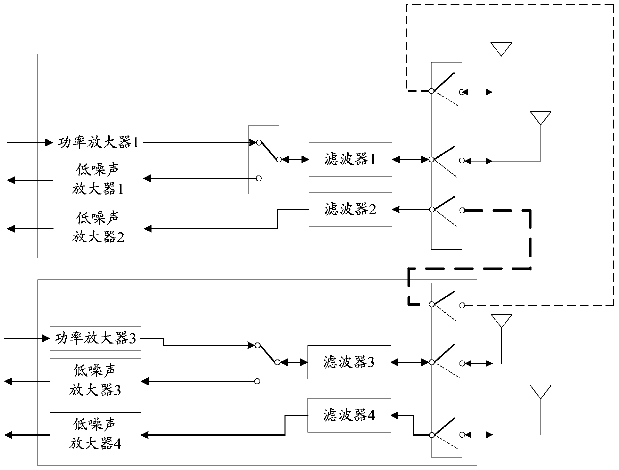
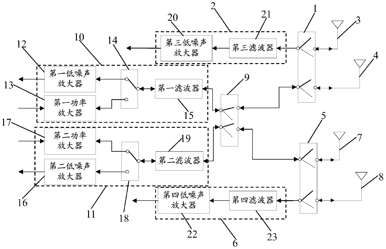
[0022] Such as figure 2 As shown, it is a schematic structural diagram of the radio frequency front-end circuit provided by the embodiment of the present invention. The radio frequency front-end circuit includes: a first double-pole double-throw switch 1; a first signal receiving circuit 2 is connected to the first target antenna in the first antenna 3 and the second antenna 4 through the first double-pole double-throw switch 1, And receive signal by...


PUM


Abstract

The invention provides a radio frequency front-end circuit and a mobile terminal. The circuit comprises a first double-pole double-throw switch; a first signal receiving circuit which is connected with one of the first antenna and the second antenna through a first double-pole double-throw switch and receives signals through the connected antenna; a second double-pole double-throw switch; a secondsignal receiving circuit which is connected with one of the third antenna and the fourth antenna through a second double-pole double-throw switch and receives signals through the connected antenna; athird double-pole double-throw switch which is respectively connected with the first double-pole double-throw switch and the second double-pole double-throw switch; a first radio frequency circuit which is connected with the third double-pole double-throw switch and comprises a signal receiving mode or a signal transmitting mode; And a second radio frequency circuit which is connected with the third double-pole double-throw switch and comprises a signal receiving mode or a signal transmitting mode. The circuit is simple in design, radio frequency layout wiring can be shortened on the basis that signal transmitting and/or receiving are/is achieved, and therefore path difference loss is reduced.

Description

technical field [0001] Embodiments of the present invention relate to the technical field of terminal applications, and in particular to a radio frequency front-end circuit and a mobile terminal. Background technique [0002] With the rapid development of Internet communication technology and the continuous popularization of mobile smart terminals, users' demand for data traffic is also increasing. From 4G's transmission rate of 100Mbps to 1Gbps, to 5G NR's peak transmission rate of up to 20Gbps, the rate increase requires 5G to have 4*4 Multiple Input Multiple Output (Multiple Input Multiple Output, MIMO) key technology. [0003] Such as figure 1 As shown, it is a schematic structural diagram of the RF front-end circuit of a 5G mobile terminal device. This circuit architecture is used to realize one transmission and four reception 1T4R and two transmission and four reception 2T4R. Among them, the layout and routing of 5G mobile terminal equipment directly affect the path l...

Claims


Application Information

Patent Timeline
Patent Type & Authority Applications(China)
IPC IPC(8): H04B7/08H04B7/06H04B7/0404H04B1/401
CPCH04B7/08H04B7/06H04B7/0404H04B1/401
Inventor 谢政男林景球
Owner VIVO MOBILE COMM CO LTD
Why Eureka
Try Eureka