Oil pumping system for oil storage tank

An oil storage tank and oil pumping technology is applied in special distribution devices, packaging, fire rescue and other directions, which can solve the problems of difficulty in extinguishing fires, difficulty in controlling fires, and troublesome handling of oil products due to the storage capacity of foam fire extinguishing agents. The effect of reducing environmental pollution and the safety of the suction process

Inactive Publication Date: 2019-06-11
ANHUI UNIVERSITY OF ARCHITECTURE
View PDF8 Cites 2 Cited by
  • Summary
  • Abstract
  • Description
  • Claims
  • Application Information

AI Technical Summary

Problems solved by technology

Now, in order to extinguish the fire of the oil storage tank, a large amount of fire extinguishing foam is often used to extinguish the fire, and the use of a large amount of foam fire extinguishing agent, the water and foam contained in the fire extinguishing agent will seriously pollute the oil in the oil storage tank, even if the fire is extinguished It will also cause the oil in the oil storage tank to be scrapped due to a large amount of water and foam, which will cause huge economic losses; and the disposal of the scrapped oil is troublesome, and if it is not handled, it will cause serious environmental pollution
On the other hand, if there is too much oil stored in the oil storage tank and it is in a burning state, it is also very difficult to control the fire, especially for large or super large oil storage tanks, the storage capacity of foam fire extinguishing agent is often difficult to extinguish the fire, only Take control of the fire and wait for the oil in the storage tank to burn completely

Method used


Image

  • Oil pumping system for oil storage tank
  • Oil pumping system for oil storage tank
  • Oil pumping system for oil storage tank

Examples


Embodiment Construction

[0027] In order to make the technical means, creative features, goals and effects achieved by the present invention easy to understand, the present invention will be further clarified below in conjunction with specific drawings.

[0028] It should be noted that, in the present invention, when an element is referred to as being "fixed" to another element, it may be directly on the other element or there may be an intervening element. When an element is referred to as being "connected to" another element, it can be directly connected to the other element or intervening elements may also be present. As used herein, the terms "vertical", "horizontal", "left", "right" and similar expressions are for the purpose of illustration only and are not intended to represent the only embodiments.

[0029] Unless otherwise defined, all technical and scientific terms used herein have the same meaning as commonly understood by one of ordinary skill in the technical field of the invention. The ...


PUM


Abstract

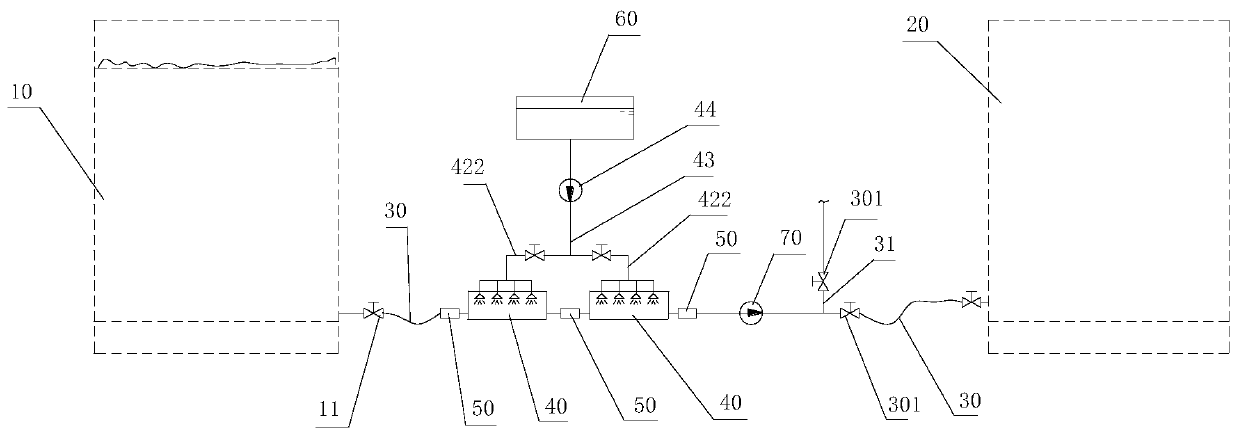
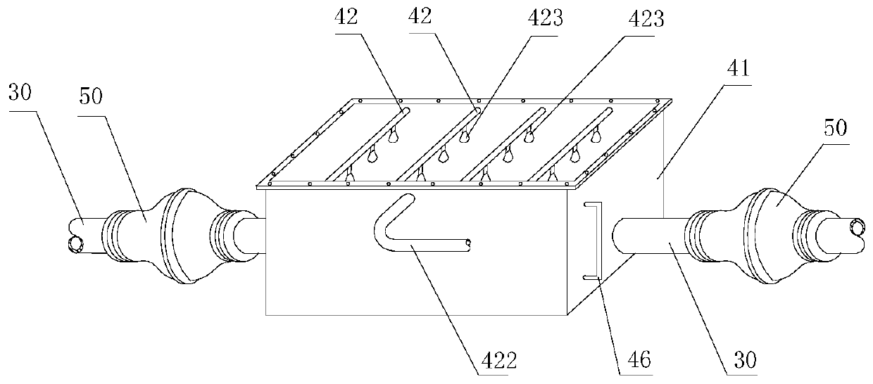
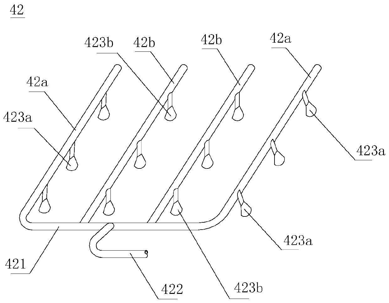
The invention belongs to the technical field of fire disaster science and firefighting and particularly relates to an oil pumping system for an oil storage tank. The oil pumping system comprises the oil storage tank, an auxiliary oil storage tank, pipelines, fire extinguishing devices and an oil suction pump, the two or more fire extinguishing devices are in series connection, and explosion-prooffire retardance valves are arranged on input end pipelines and output end pipelines of the fire extinguishing devices and pipelines between the adjacent fire extinguishing devices correspondingly; each fire extinguishing device comprises an oil storage trough and a fire extinguishing row arranged at a trough opening in the upper part of the oil storage trough, the fire extinguishing rows communicate with a firefighting water pool through a water supply pipe and a firefighting water pump, the positions of all the oil storage troughs are sequentially lowered in the direction away from the oil storage tank, the oil storage tank discharges oil to the oil storage troughs through the pipelines, and when the oil quantity in the oil storage troughs approaches to the one-second height, the oil suction pump is started to pump an oil product into the auxiliary oil storage tank. The technical requirement that the oil product in the oil storage tank suffering from the fire disaster is pumped and transferred to the other safe oil storage tanks in time can be met, burning of the other oil storage tanks is avoided, and the pumping process is safe and reliable.

Description

technical field [0001] The invention belongs to the field of fire science and fire protection technology, and in particular relates to an oil pumping system for an oil storage tank. Background technique [0002] In recent years, with the rapid development of my country's automobile industry, a large amount of fuel oil needs to be consumed every year. In this process, a large number of oil storage tanks need to be built to meet the use requirements. A fuel tank fire occurred. Now, in order to extinguish the fire of the oil storage tank, a large amount of fire extinguishing foam is often used to extinguish the fire, and the use of a large amount of foam fire extinguishing agent, the water and foam contained in the fire extinguishing agent will seriously pollute the oil in the oil storage tank, even if the fire is extinguished It will also cause the oil in the oil storage tank to be scrapped due to being mixed with a large amount of water and foam, which will cause huge economi...

Claims


Application Information

Patent Timeline
Patent Type & Authority Applications(China)
IPC IPC(8): A62C3/06A62C4/00A62C31/02A62C31/28B67D7/04B67D7/36
Inventor 夏云春苏少卿张霖
Owner ANHUI UNIVERSITY OF ARCHITECTURE
Why Eureka
Try Eureka