Air inlet assembly of gas engine

A technology of gas engine and air intake components, which is applied in the direction of engine components, combustion engines, fuel air inlets, etc., can solve problems such as potential safety hazards, and achieve high safety, improved sealing, and good sealing performance

Inactive Publication Date: 2020-03-24
四川华气动力有限责任公司
View PDF10 Cites 0 Cited by
  • Summary
  • Abstract
  • Description
  • Claims
  • Application Information

AI Technical Summary

Problems solved by technology

[0003] Aiming at the above-mentioned technical problem that there is a great potential safety hazard in the aging air leakage of the existing throttle mechanical seal rubber, the present invention provides a gas engine intake assembly, which adds an air seal on the basis of the throttle mechanical seal, and can avoid Potential safety hazards caused by leakage, with the characteristics of good sealing and high safety

Method used


Image

  • Air inlet assembly of gas engine

Examples


Embodiment 1

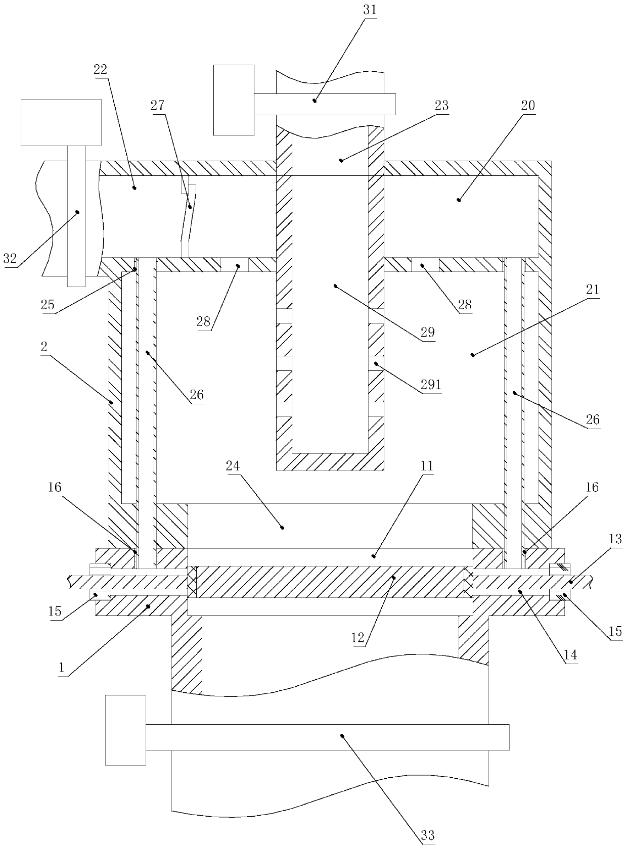
[0026] A gas engine intake assembly includes a throttle valve 1. Specifically, the position of the throttle valve 1 in the gas engine intake system and the connection relationship with other components are the same as those of the existing gas engine intake system. The throttle valve 1 includes a vent 11 and a valve plate 12, the valve plate 12 is provided with a rotating shaft 13, the side wall of the vent hole 11 is provided with two rotating shaft holes 14, and both ends of the rotating shaft 13 are respectively inserted in the rotating shaft holes In 14, a mechanical sealing device 15 is provided at the outer end of the shaft hole 14. Similar to the existing throttle valve, the opening size of the vent hole 11 of the throttle valve 1 is controlled by the rotation angle of the valve plate 12 to control the flow rate of the mixed gas entering the combustion chamber of the gas engine. The difference is that the hole wall of the shaft hole 14 of the throttle valve 1 is provided...

Embodiment 2

[0033] Based on Example 1, the compressed air inlet 22 is provided with a one-way valve 27, and the one-way valve 27 is located between the second inlet 16 and the outlet end of the compressed air inlet 22 to prevent the mixer Gas backflow in 2.

[0034] Preferably, the inlet end of the gas inlet 23 is connected to a first meter 31, which is used to monitor the amount of gas entering the mixer 2; the inlet end of the compressed air inlet 22 is connected to There is a second meter 32, the second meter 32 is used to monitor the amount of air entering the mixer 2; the mixed gas outlet 24 is connected to a third meter 33, the third meter 33 is used to monitor the mixer 2 The amount of gas entering the combustion chamber of a gas engine.

[0035] By comparing the sum of the readings of the first meter 31 and the second meter 32 with the reading of the third meter 33, it can be judged whether the gas engine intake system is leaking, and the gas engine intake system can be overhauled in ...

Embodiment 3

[0037] On the basis of Embodiment 1 or Embodiment 2, the mixer 2 further includes a compressed air inlet chamber 20, which communicates with the mixing chamber 21 through a number of connecting holes 28, so that the compressed air and The gas is evenly mixed.

[0038] Preferably, the compressed air inlet cavity 20 and the mixing cavity 21 are both cylindrical shaped cavities. The connecting holes 28 are evenly distributed along the circumferential direction of the axis of the mixing chamber 21 to further improve the uniformity of the mixing of compressed air and fuel gas.

[0039] Preferably, a gas inlet pipe 29 is provided in the middle of the compressed air inlet cavity 20. One end of the gas inlet pipe 29 is in communication with the gas inlet port 23, and the other end of the gas inlet pipe 29 is located in the mixing chamber 21. One end of the gas introduction pipe 29 located in the mixing chamber 21 is closed, and the side wall of the gas introduction pipe 29 located in the ...


PUM


Abstract

The invention relates to the technical field of gas engines, in particular to an air inlet assembly of a gas engine. The adopted technical scheme is as follows: the air inlet assembly of the gas engine comprises a throttle valve; the throttle valve comprises a vent hole and a valve plate; the valve plate is provided with a rotating shaft; two rotating shaft holes are formed in the side wall of thevent hole; the two ends of the rotating shaft are inserted into the rotating shaft holes respectively; a mechanical sealing device is arranged at the outer end of the rotating shaft hole; a first airinlet is formed in the hole wall of the rotating shaft hole of the throttle valve; the first air inlet is located in the inner side of the mechanical sealing device; and the first air inlet is used for being connected with a compressed air source. High-pressure compressed air is used for conducting air sealing on the rotating shaft hole, air sealing is added on the basis of mechanical sealing ofthe throttle valve, potential safety hazards caused by leakage of mixed air can be avoided, and the throttle valve has the advantages of being good in sealing performance and high in safety.

Description

Technical field [0001] The invention relates to the technical field of gas engines, in particular to an air intake component of a gas engine. Background technique [0002] Gas engines usually use natural gas as fuel. Compared with ordinary oil engines, they are energy-saving, economical, and environmentally friendly. Therefore, they are more and more widely used. After the gas engine gas is released from the gas source cylinder, it passes through the high-pressure cut-off generator, stabilizer, gas filter, heat exchanger, gas thermostat and metering valve in sequence, and then mixes with the pressurized air. After mixing in the device, it is sent into the combustion chamber through the throttle. Existing throttle valves have a butterfly valve structure. A shaft hole for installing a butterfly valve shaft is provided on the side wall of the throttle hole vent hole. The end of the valve disc shaft of the butterfly valve is inserted in the shaft hole and is rotatably connected with...

Claims


Application Information

Patent Timeline
Patent Type & Authority Applications(China)
IPC IPC(8): F02M35/10F02D9/10F02M21/04F02B77/08
CPCF02M35/10006F02M35/1015F02M35/10386F02D9/106F02M21/042F02B77/083Y02T10/30
Inventor 周行
Owner 四川华气动力有限责任公司
Why Eureka
Try Eureka