Automatic rising and falling wind resistance high pressure fine water mist fire extinguishing device

A high-pressure water mist and fire-extinguishing technology, applied in fire rescue and other directions, can solve the problems of reducing fire-extinguishing efficiency, being easily blown away by wind, and low fire-extinguishing performance, saving space, improving fire-extinguishing efficiency and performance, and fire-extinguishing efficiency high effect

Active Publication Date: 2019-06-11
SHANGHAI UNIV OF ENG SCI
View PDF5 Cites 4 Cited by
  • Summary
  • Abstract
  • Description
  • Claims
  • Application Information

AI Technical Summary

Problems solved by technology

However, in some semi-open large indoor spaces, once a fire breaks out, strong crosswinds are likely to occur. Traditional nozzles with traditional fine water mist nozzles have a small atomization angle and are easily blown away by the wind, resulting in low fire extinguishing performance.
Moreover, for a semi-open large indoor space, because of its high floor height, the existing fire extinguishing nozzles at a higher level will reduce the efficiency of fire extinguishing

Method used


Image

  • Automatic rising and falling wind resistance high pressure fine water mist fire extinguishing device
  • Automatic rising and falling wind resistance high pressure fine water mist fire extinguishing device
  • Automatic rising and falling wind resistance high pressure fine water mist fire extinguishing device

Examples


Embodiment Construction

[0027] The present invention will be described in detail below in conjunction with the accompanying drawings and specific embodiments. This embodiment is carried out on the premise of the technical solution of the present invention, and detailed implementation and specific operation process are given, but the protection scope of the present invention is not limited to the following embodiments.

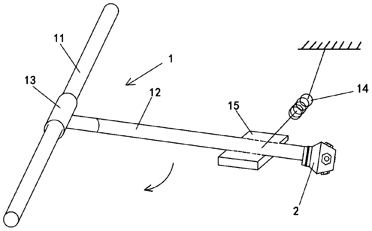
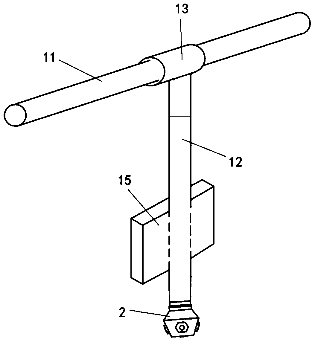
[0028] Such as figure 1 and figure 2 As shown, this embodiment provides an automatic wind-resistant high-pressure water mist fire extinguishing device, including a lifting mechanism 1 and a fire extinguishing nozzle 2 .

[0029] Lifting mechanism 1 comprises main water pipe 11 , branch water pipe 12 , T-shaped three-way pipe 13 , spring 14 and water storage tank 15 . The main water pipe 11 is connected to both ends of the T-shaped three-way pipe 13 in the transverse direction through an existing rotary sealing method, so that the T-shaped three-way pipe 13 can rotate along the axia...


PUM


Abstract

The invention relates to an automatic rising and falling wind resistance high pressure fine water mist fire extinguishing device. The automatic rising and falling wind resistance high pressure fine water mist fire extinguishing device comprises a lifting mechanism and a fire extinguishing spraying head. The lifting mechanism comprises a main water tube, branched water tubes, a T-shaped three-way tube, a spring and a water storage tank, the main water tube is rotatably connected to the two ends of the T-shaped three-way tube in the horizontal direction in a sealing mode, one ends of the branched water tubes are connected with one end of the T-shaped three-way tube in the longitudinal direction, the fire extinguishing spraying head is connected to the other ends of the branched water tubes,the water storage tank is arranged on the branched water tubes, and the branched water tubes are connected with the top of a space in which a connecting device is located through the spring. The fireextinguishing spraying head comprises a rotational flow pressurizing module and a spray nozzle module, the rotational flow pressurizing module comprises a tangential slot unit and a direct incidence interception unit, the tangential slot unit is arranged in the branched water tubes and connected to the mounting end, and the direct incidence interception unit is arranged in the branched water tubesand connected with the tangential slot unit. Compared with the prior art, the automatic rising and falling wind resistance high pressure fine water mist fire extinguishing device can perform efficient fire extinguishing when fire disaster occurs in a perpendicular state; and efficient fire extinguishing further can be carried out in a windy environment, and the good integral fire extinguishing performance is guaranteed.

Description

technical field [0001] The invention relates to a fire extinguishing device, in particular to an automatic rising and falling anti-wind and high-pressure fine water mist fire extinguishing device. Background technique [0002] As a new fire extinguishing system, the high pressure water mist fire extinguishing system has been widely used in the field of fire protection. Water mist nozzle is an important part of water mist fire extinguishing system, and its good atomization performance is the guarantee of fire extinguishing efficiency. However, in some semi-open large indoor spaces, once a fire breaks out, strong crosswinds are likely to occur. Traditional fine water mist nozzles have a small atomization angle and are easily blown away by the wind, resulting in low fire extinguishing performance. Moreover, for a semi-open large indoor space, because of its high floor height, the existing fire extinguishing nozzles at a relatively high level will reduce the efficiency of fire ...

Claims


Application Information

Patent Timeline
Patent Type & Authority Applications(China)
IPC IPC(8): A62C31/02A62C31/28
Inventor 刘畅石丽娜樊恩玺王庆渠韩路亚
Owner SHANGHAI UNIV OF ENG SCI
Why Eureka
Try Eureka