A high-end opto-mechanical-based production device
A production device, optical electromechanical technology, applied to mixers with rotating stirring devices, mixers, feed, etc., can solve the problems of being unable to stop and use immediately, difficulty in reducing production costs, and inability to integrate the production of production devices, etc., to achieve The effect of improving production efficiency, saving feeding time, and saving intermediate transportation costs
- Summary
- Abstract
- Description
- Claims
- Application Information
AI Technical Summary
Problems solved by technology
Method used
Image
Examples
Embodiment 1
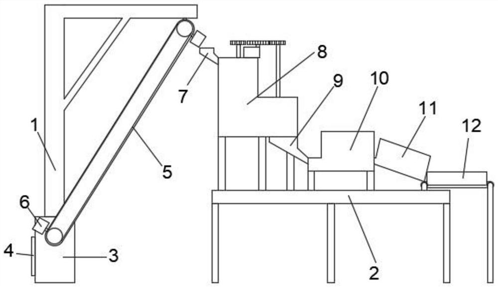
[0025] Embodiment 1: refer to figure 1 ;
[0026] A high-end production device based on optomechanical electronics, including a support 1 and a production table 2, a feed conveyor belt 5 is fixedly installed on the support 1, a main control box 3 is fixedly connected to the bottom of the support 1, and a main control box 3 is installed inside the main control box 3. Based on the optical electromechanical intelligent production system, the control panel 4 is fixedly installed on the left side of the main control box 3, the control panel 4 is electrically connected to the intelligent production system, and the lower end side of the feeding conveyor belt 5 is connected to the transmission motor in the main control box 3 in rotation , the transmission motor is electrically connected to the control panel 4, and the opposite ends of the feeding conveyor belt 5 are respectively fixedly equipped with feeding troughs 6; the production table 3 is fixedly installed with a mixing device 8...
Embodiment 2
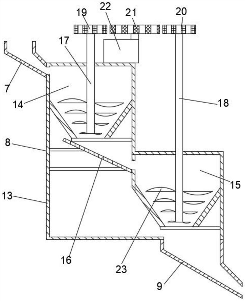
[0029] Embodiment 2: refer to figure 2 , the basis of the embodiment 1 is different in that;
[0030] The mixing and stirring device 8 includes a stirring shell 13, an induction rotating motor 22 is fixedly installed on the top of the stirring shell 13, the induction rotating motor 22 is electrically connected with the intelligent production system, the induction rotating motor 22 is fixedly connected with a rotating gear 21, and the stirring shell 13 is respectively A first stirring chamber 14 and a second stirring chamber 15 are provided, and the inner middle end of the stirring shell 13 is fixedly connected with an extension plate 16 through a connecting rod. The outlet at the lower end of 14 is matched with the upper end of the extension plate 16, the right side of the bottom of the second stirring chamber 15 is connected with the discharge hopper 9, the upper left end of the second stirring chamber 15 is matched with the lower end of the extension plate 16; the top of th...
Embodiment 3
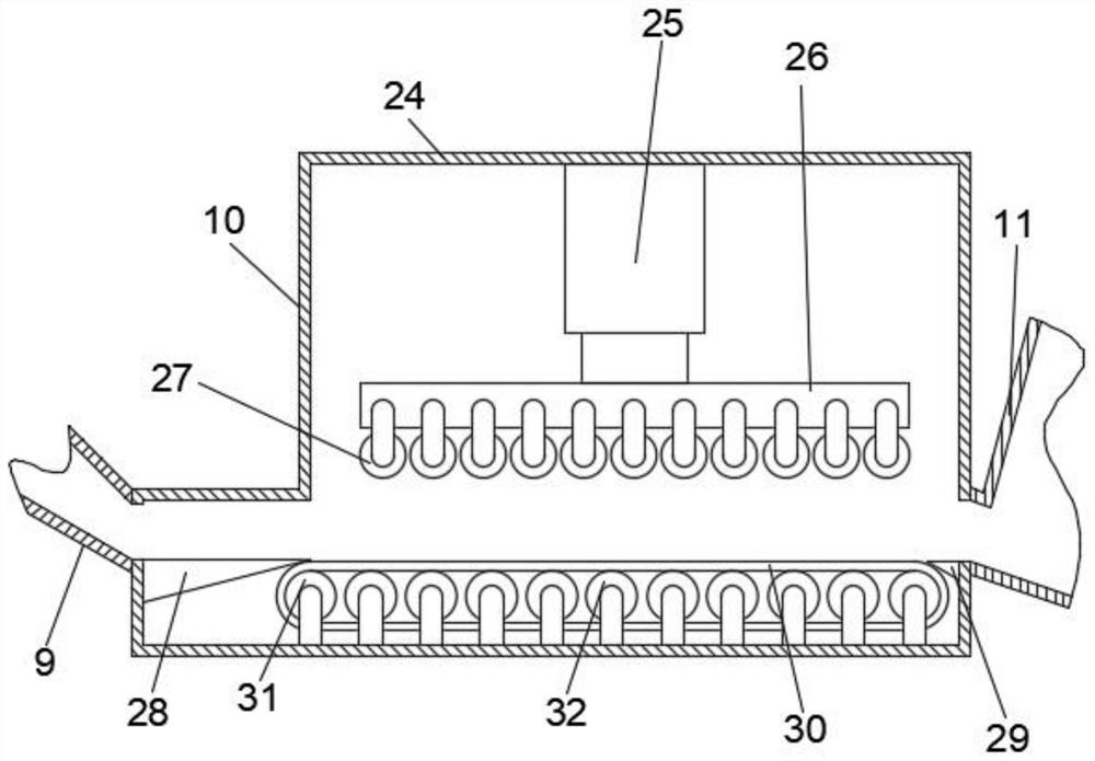
[0032] Embodiment 3: refer to image 3 , the basis of the embodiment 1 is different in that;
[0033] The rolling device 10 includes a rolling box 24, the inlet of the rolling box 24 is connected with the outlet of the discharge hopper 9, and the lower end of the rolling box 24 is fixedly connected with the inner wall of the entrance to facilitate the advancement of materials. , the rolling box 24 is fixedly connected to the inner wall of the outlet with a material discharge extension block 29 that is convenient for the material to be released. A moving belt 30 is arranged between the feeding extension block 28 and the output extension block 29, and the two ends of the moving belt 30 are flexibly connected. There are driving rollers 31, and the middle part of the moving belt 30 is movably connected with multiple sets of support rollers 32 for rolling support; the inner top of the rolling box 24 is fixedly connected with an electronically controlled hydraulic rod 25, and the lo...
PUM
 Abstract
Description
Claims
Application Information
 - R&D
- Intellectual Property
- Life Sciences
- Materials
- Tech Scout
- Unparalleled Data Quality
- Higher Quality Content
- 60% Fewer Hallucinations
Browse by: Latest US Patents, China's latest patents, Technical Efficacy Thesaurus, Application Domain, Technology Topic, Popular Technical Reports.
© 2025 PatSnap. All rights reserved.Legal|Privacy policy|Modern Slavery Act Transparency Statement|Sitemap|About US| Contact US: help@patsnap.com


