

Linear friction welding device
A linear friction welding and articulation technology, which is applied in welding equipment, non-electric welding equipment, metal processing equipment, etc., can solve the problems of expensive linear friction welding equipment, increase reciprocating motion frequency, reduce driving force, and increase heat Effect
Inactive Publication Date: 2019-06-11
NANCHANG HANGKONG UNIVERSITY
View PDF13 Cites 1 Cited by
- Summary
- Abstract
- Description
- Claims
- Application Information
AI Technical Summary
Problems solved by technology
As a welding method with great potential application prospects, the reason why it has not been widely used after nearly 20 years of development is that linear friction welding equipment is expensive
Method used
View moreImage
Smart ImageViewing Examples

Examples
Embodiment 2
[0034] The difference is that using Figure 6 In the middle cam structure, the double cam bottom plate moves back and forth five times.
Embodiment 3
[0036] The difference is that using Figure 7 In the middle cam structure, the double cam bottom plate moves back and forth six times left and right.
Login to View More PUM
 Abstract
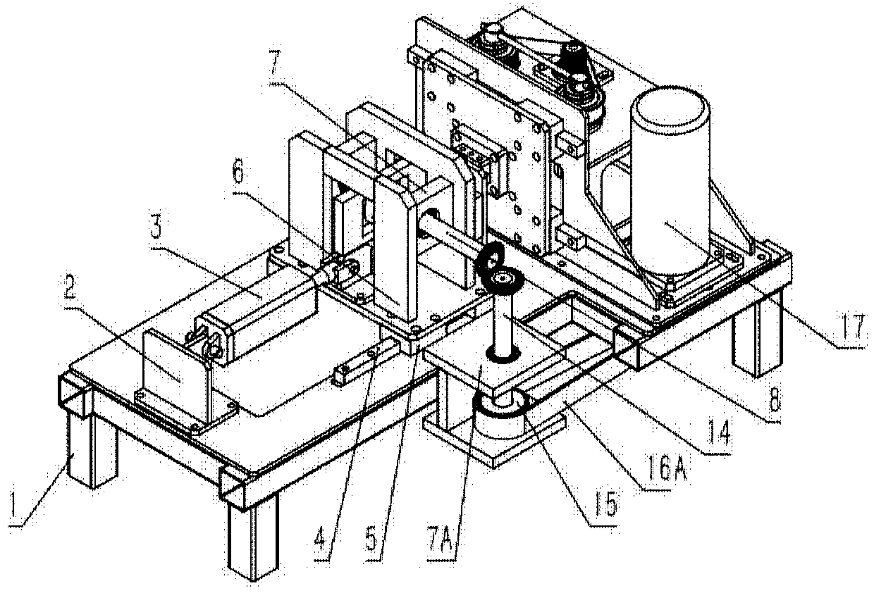
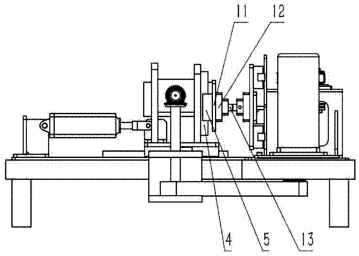
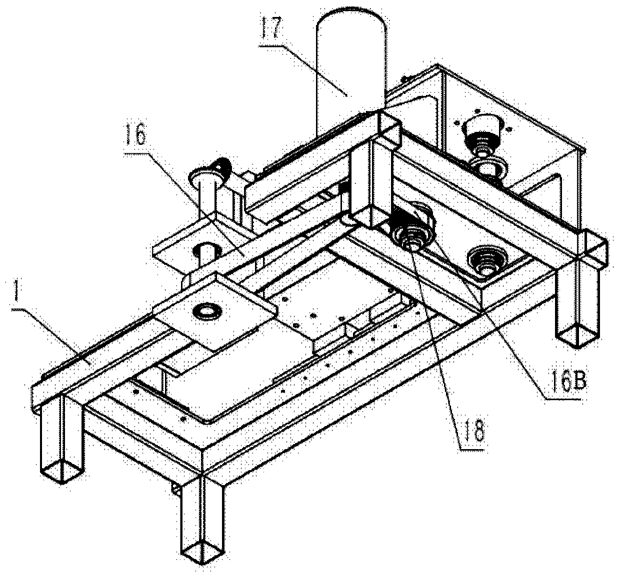
The invention discloses a linear friction welding device. The linear friction welding device comprises a single-cam module, a double-cam module, a driving module, a feeding module and a base; the front end of the base is fixedly connected with the feeding module; the feeding module is hinged with the single-cam module; the double-cam module is arranged on the back side of the single-cam module; the driving module is arranged on the left side of the base; the driving module drives the single-cam module and the double-cam module through a first driving synchronous belt A and a second driving synchronous belt B ; and the single-cam module and the double-cam module are fixedly connected with the base. The linear friction welding device has the following advantages: the single-cam module drivesworkpieces to be welded to perform an up-down reciprocating motion; the double-cam module drives the workpieces to be welded to perform a left-right reciprocating motion; and under the condition of identical welded parts, the needed driving force is greatly reduced.
Description
technical field [0001] The invention specifically relates to a linear friction welding device. Background technique [0002] Linear friction welding is a solid-phase welding technology. Under the action of welding pressure, one of the weldments moves linearly reciprocating with a certain amplitude A and frequency f in a straight line direction relative to the other weldment, and friction bonding and shearing occur. Friction heat is generated, and the temperature of the friction interface rises. When the friction surface reaches a viscoplastic state, the metal in the welding zone undergoes plastic flow under the action of pressure to form flash. When the temperature and deformation of the friction welding zone reach a certain level, the weldment is aligned. And applying upsetting pressure, the metal in the welding zone is welded together through mutual diffusion and recrystallization, and the entire welding process is completed. The process mainly includes the following five ...
Claims
Login to View More Application Information
Patent Timeline
 IPC IPC(8): B23K20/12B23K20/26
Inventor朱圣远王善林胡锦扬陈玉华徐嘉鹏黄永德柯黎明
OwnerNANCHANG HANGKONG UNIVERSITY