Clamping-installing type quick clamping mechanism and installation method thereof

A clamping mechanism and clamping technology, which is applied in the direction of workpiece clamping devices and manufacturing tools, can solve the problems of insufficient flexibility of the clamping device and narrow application range, and achieve the effect of flexible pressure adjustment and wide application

Active Publication Date: 2019-06-11
安徽华中机械配套工程有限公司
View PDF10 Cites 2 Cited by
  • Summary
  • Abstract
  • Description
  • Claims
  • Application Information

AI Technical Summary

Problems solved by technology

[0004] The purpose of the present invention is to provide a clamping type quick clamping mechanism and its installation method, through which the existing clamping device is not flexible enough and the application range is narrow.

Method used


Image

  • Clamping-installing type quick clamping mechanism and installation method thereof
  • Clamping-installing type quick clamping mechanism and installation method thereof
  • Clamping-installing type quick clamping mechanism and installation method thereof

Examples


Embodiment 1

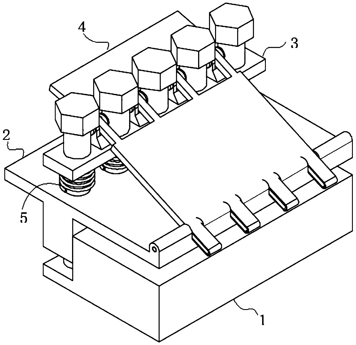
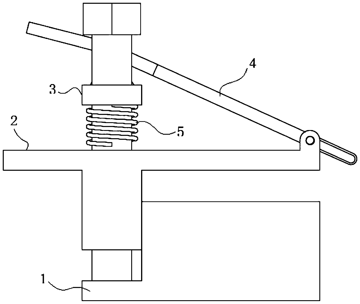
[0041] see figure 1 and 2 As shown, the present invention is a clamping type quick clamping mechanism, including a first clamping plate 1 and a second clamping plate 2, and a pressing plate 3 is arranged on the second clamping plate 2;

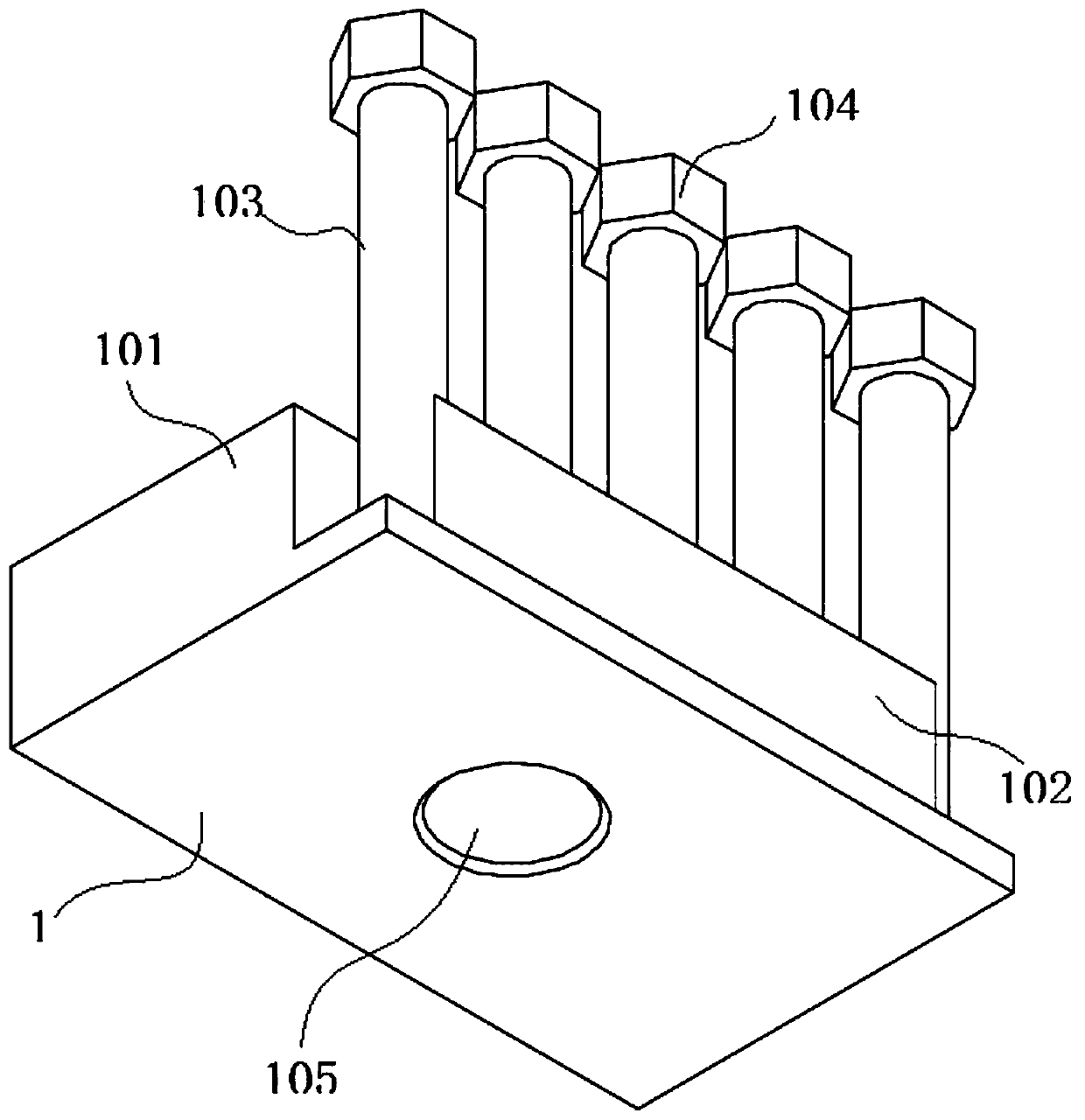
[0042] Such as image 3 As shown, one surface of the first splint 1 is provided with clamping blocks 101 and guide blocks 102, and the opposite surface of the first splint 1 is provided with connecting holes 105; the surface of the guide block 102 is uniformly provided with several guide posts 103; One end is provided with a limit adjustment block 104; the connecting hole 105 is connected with a rod, and the rod adopts a telescopic rod or a threaded rod to support the first splint 1; the limit adjustment block 104 can generally be realized by using a nut, or by setting a double The nut is used to adjust the clamping pressure between the first splint 1 and the second splint 2 by adjusting the position of the nut on the guide column 103 .

[...

Embodiment 2

[0056] see figure 1 and 2 As shown, the present invention is a clamping type quick clamping mechanism, including a first clamping plate 1 and a second clamping plate 2, and a pressing plate 3 is arranged on the second clamping plate 2;

[0057] Such as image 3 As shown, one surface of the first splint 1 is provided with clamping blocks 101 and guide blocks 102, and the opposite surface of the first splint 1 is provided with connecting holes 105; the surface of the guide block 102 is uniformly provided with several guide posts 103; One end is provided with a limit adjustment block 104; the connecting hole 105 is connected with a rod, and the rod adopts a telescopic rod or a threaded rod to support the first splint 1; the limit adjustment block 104 can generally be realized by using a nut, or by setting a double The nut is used to adjust the clamping pressure between the first splint 1 and the second splint 2 by adjusting the position of the nut on the guide column 103 .

[...


PUM


Abstract

The invention discloses a clamping-installing type quick clamping mechanism and an installation method thereof, and relates to the technical field of mechanical clamps. The clamping-installing type quick clamping mechanism comprises a first clamping plate and a second clamping plate, wherein the second clamping plate is provided with a pressing plate; by pressing a buckling plate at one end of a lever plate and extruding an elastic element, the spacing between a clamping block and the second clamping plate is enlarged, the clamping block and the second clamping plate are directly clamped to aobject to be clamped, and the pressure of the buckling plate is removed to enable the clamping block and the second clamping plate to fix the object to be clamped under the elastic force of the elastic element. The clamping-installing type quick clamping mechanism is provided with a group of clamping plate to quickly clamp and install the superposed periphery of a plurality of sets of plates, thefunction of clamping is achieved by a lever and a spring group, pressure regulation is flexible, and the application is wide.

Description

technical field [0001] The invention belongs to the technical field of mechanical clamps, and in particular relates to a clamping type quick clamping mechanism and an installation and application method of the clamping type fast clamping mechanism. Background technique [0002] Existing disclosed actuated or manual clamping devices have three functions: open and close the mold, eject the plastic part, and have sufficient force to keep the mold closed during injection to resist the pressure of the melt in the mold. The clamping force required per unit projected area of ​​the part is usually 30-70MPa (about 2-5t / in2). The pressure generated during filling and the force on the core due to the shrinkage of the part may cause the part to stick, thus causing two Difficulty separating the mold halves. The size of the initial mold opening force depends on the filling pressure and the geometric dimensions of the material parts (depth and demoulding slope), which is approximately equ...

Claims


Application Information

Patent Timeline
IPC IPC(8): B25B11/00
Inventor 雷振友
Owner 安徽华中机械配套工程有限公司
Why Eureka
Try Eureka