
Double-cylinder nailing method

A double-cylinder, main-cylinder technology, applied in the field of nailing, can solve the problems of inability to realize automatic gas compensation, increase in equipment weight and volume, and difficulty in achieving effective compression, and achieve simple and effective control methods, improve nailing power, simplify structure effect

Pending Publication Date: 2022-07-15
SICHUAN UNIVERSITY OF SCIENCE AND ENGINEERING +2
View PDF12 Cites 0 Cited by
  • Summary
  • Abstract
  • Description
  • Claims
  • Application Information

AI Technical Summary

Problems solved by technology

[0005] Firstly, this technology uses a crank-rocker structure for gas compression energy storage, but this structure has difficulties in achieving effective compression of high-pressure gas , resulting in less nailing power
In order to improve the nailing power, the volume of the magnetic parts must be increased, but this will lead to an increase in the weight and volume of the equipment.
[0006]Secondly, this technology can also drive the adjustable valve plug to change the size of the air chamber cavity of the additional small cylinder by turning the screw mechanism to adjust the nailing power However, due to the small volume of the small cylinder itself, it also has the problem of a small adjustable range of power
[0007]Finally, when the gas in the cylinder leaks slightly, it cannot realize the automatic compensation of the gas, which will lead to the decrease of nailing power

Method used


Image

  • Double-cylinder nailing method
  • Double-cylinder nailing method
  • Double-cylinder nailing method

Examples


Embodiment 1

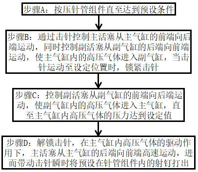
[0079] The invention discloses a double-cylinder nailing method, such as figure 1 shown, it includes the following steps:

[0080] Step A: Startup Preparation

[0081] The needle tube assembly is pressed until a preset condition is reached, and the preset condition is mainly the pressing pressure or the movement displacement of the needle tube in the needle tube assembly, and its specific value can be set according to actual needs.

[0082] Step B: Firing pin in place

[0083] First control the firing pin to move to the rear end of the main cylinder, and then drive the main piston to move from the front end of the main cylinder to the rear end through the firing pin, while the auxiliary piston moves from the rear end of the auxiliary cylinder to the front end, so that the high-pressure gas in the main cylinder enters the auxiliary cylinder. Air cylinder, when the firing pin moves to the set limit position, the firing pin enters the limit state.

[0084] Step C: Pressurized ...

Embodiment 2

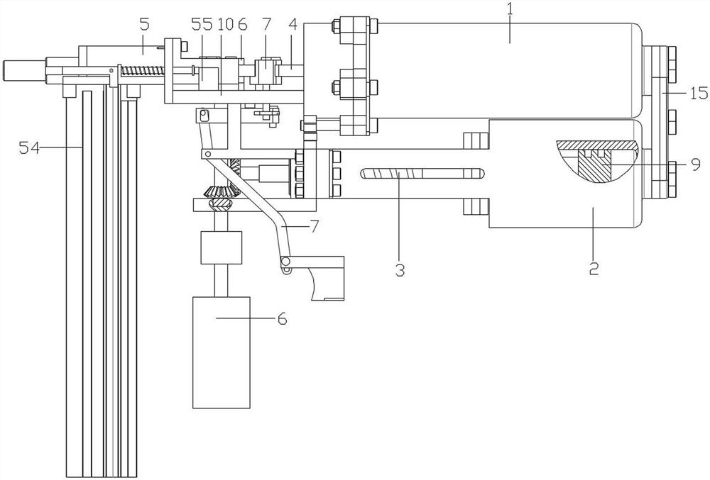
[0090] The invention discloses a double-cylinder nailing method, such as Figure 1-4 As shown, the method includes a main cylinder 1 , a secondary cylinder 2 , a linear motion mechanism 3 , a sensor 55 , a firing needle 4 , a needle tube assembly 5 , a driving mechanism 6 and a limit release mechanism 7 . in,

[0091] The master cylinder 1 includes a cylinder block 43, a cylinder head 44, a shock absorbing pad 45 and a washer 46. The cylinder head 44 is sealed and fixed on the cylinder block 43 by bolts. The washer 46 is provided with bolt holes around it, and the washer 46 passes through the bolts and the bolt holes. It is fixed between the cylinder head 44 and the cylinder block 43, and the shock absorbing pad 45 is fixed in the cylinder head 44 to reduce the vibration during the use of the injection gun. The cylinder head 44 has a certain internal space. In order to improve the damping effect, it is preferable that the size and shape of the damping pad seat 45 are adapted ...

Embodiment 3

[0112] On the basis of Embodiment 2, this embodiment further defines the structures of the drive mechanism 6, the limit release mechanism 7 and the linear motion mechanism 3, as follows:

[0113] like Figure 2-4 As shown, the drive mechanism 6 includes a motor 16, a first reducer 17, a second reducer 18, a one-way clutch (not shown in the figure), a transmission shaft 19, a toggle assembly 20 and a bevel gear 21, wherein, The motor 16 , the first reducer 17 , the second reducer 18 , the one-way clutch, the transmission shaft 19 and the toggle assembly 20 are connected in sequence, and preferably the one-way clutch is wrapped in the second reducer 18 . Of course, as required, a third speed reducer may also be provided at the rear end of the one-way clutch. The toggle assembly 20 is arranged on one side of the firing pin 4 for controlling the action of the firing pin 4 through the toggle teeth 11, and the bevel gear 21 is arranged between the first reducer 17 and the second re...


PUM


Abstract

The invention discloses a double-air-cylinder nailing method. The method comprises the steps that A, a needle tube assembly is pressed till a preset condition is met; b, driving a main piston to move from the front end to the rear end of the main air cylinder through the firing pin, meanwhile, moving an auxiliary piston from the rear end to the front end of the auxiliary air cylinder, enabling high-pressure gas in the main air cylinder to enter the auxiliary air cylinder, and enabling the firing pin to enter a limiting state when the firing pin moves to a set position; c, the auxiliary piston moves from the front end of the auxiliary air cylinder to the rear end of the auxiliary air cylinder, so that the high-pressure gas in the auxiliary air cylinder enters the main air cylinder till the pressure of the high-pressure gas in the main air cylinder reaches a set value; and D, limiting of the firing pin is relieved, the main piston moves at a high speed from the rear end of the main air cylinder to the front end of the main air cylinder under the driving effect of the high-pressure gas in the main air cylinder, and the firing pin is driven to instantly shoot out the shoot nail preset in the needle tube assembly. According to the method, the nailing power can be automatically adjusted according to needs, and the micro-leakage amount can be automatically compensated when gas in a cylinder is subjected to micro-leakage, so that the better nailing power is ensured; and meanwhile, the product structure is simplified, and the size is reduced.

Description

technical field [0001] The invention belongs to the technical field of nailing, and in particular relates to a double-cylinder nailing method. Background technique [0002] A nailer is a fastening tool that uses blank bullets, gas or compressed air as power to drive nails into buildings. Compared with the traditional methods of pre-embedding and fixing, drilling and pouring, bolting, welding, etc., the nailer has many advantages, such as: it is convenient for on-site and high-altitude operations, fast operation, and short construction period, which can greatly reduce the labor intensity of workers. Reliable and safe, save money, reduce construction costs, and even solve some construction problems that were difficult to solve in the past. [0003] Double-cylinder electric nail driver is a commonly used nail-shooting fastening technology. Because it can effectively and stably achieve nail-shooting fastening, it is more and more widely used in the construction industry or othe...

Claims


Application Information

Patent Timeline
IPC IPC(8): B25C1/04B25C7/00
CPCB25C1/04B25C1/041B25C7/00
Inventor 文华斌张柏洋陶静刘杰何平杨余李正东
Owner SICHUAN UNIVERSITY OF SCIENCE AND ENGINEERING
Learn More