Insulating mounting robot for power distribution cabinet

A technology for robots and power distribution cabinets, applied in the directions of manipulators, switchgear, electrical components, etc., can solve problems such as the inability to achieve fully automatic insulation installation, and achieve the effect of improving mobility

Active Publication Date: 2019-06-11
江苏华翔控股股份有限公司
View PDF7 Cites 8 Cited by
  • Summary
  • Abstract
  • Description
  • Claims
  • Application Information

AI Technical Summary

Problems solved by technology

[0002] Nowadays, power distribution cabinets are widely used in various fields. For public facilities, high-voltage power distribution cabinets are usually placed in one place, and when high-voltage power distribution cabinets are installed on the ground, they need to be installed on an insulating board , and the power distribution cabinet is connected to the insulating plate and the ground through bolts. Now, a power distribution cabinet insulation installation robot is designed. There is a design of a power distribution cabinet insulation installation robot. For example, the patent application number CN201621446845.4 discloses a A new type of power distribution cabinet installation frame, the device assists the positioning and installation of the power distribution cabinet, but it cannot realize fully automatic insulation installation; for example, the patent number CN201420123824. Install, but manual operation is required

Method used


Image

  • Insulating mounting robot for power distribution cabinet
  • Insulating mounting robot for power distribution cabinet
  • Insulating mounting robot for power distribution cabinet

Examples


Embodiment Construction

[0023] The technical solutions of the present invention will be further specifically described below through the embodiments and in conjunction with the accompanying drawings.

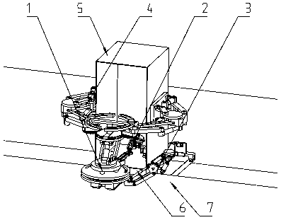
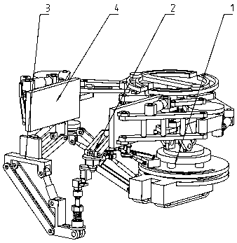
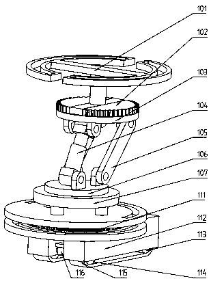
[0024] Example figure 1 , figure 2 , image 3 , Figure 4 , Figure 5 , Image 6 , Figure 7As shown, a power distribution cabinet insulation installation robot includes a main part 1, a twisting part 2, a fixed part 3, and a clamping part 4. The main part 1 includes a limit plate 101, a half gear 102, a half gear seat 103, a second An electric cylinder 104, lifting rod 105, rotating lifting disc 106, rotating base 107, chassis, first gear 108, first stepper motor 109, second gear 110, third gear 111, walking frame 112, driven wheel 113, Drive wheel 114, walking belt 115, two-way asynchronous motor 116; the limit plate 101 is fixedly installed on the upper end surface of the half gear seat 103; two half gears 102 are fixedly installed on the upper end surface of the half gear seat 103; the first...


PUM


Abstract

The invention provides an insulating mounting robot for a power distribution cabinet. The insulating mounting robot comprises a main body part, a screwing part, a fixing part and a clamping part; themain body part comprises a limiting disc, semi-gears, a semi-gear seat, a first electric cylinder, a lifting rod, a rotary lifting disc, a rotating base, a base plate, a first gear, a first stepping motor, a second gear, a third gear, a travelling frame, a driven wheel, a driving wheel, a travelling belt and a two-way asynchronous motor; the screwing part is provided with a parallel mechanism to provide sufficient degrees of freedom for a joint, motion such as rotation, stretching out and drawing back can be achieved, and a nut can be aligned with a bolt and is tightly screwed; magnets are mounted on the inner sides of a nut sleeve of the screwing part and a bolt sleeve of the fixing part, and thus it can be guaranteed that the bolt and the nut do not fall off in the moving process; and the fixing part is provided with a parallel mechanism, the functions such as rotation, stretching out and drawing back can be achieved, and the degree of freedom needed when the bolt is inserted into ahole from the lower part can be met.

Description

technical field [0001] The invention relates to the technical field of power distribution cabinets, in particular to a robot for insulating and installing power distribution cabinets. Background technique [0002] Nowadays, power distribution cabinets are widely used in various fields. For public facilities, high-voltage power distribution cabinets are usually placed in one place, and when high-voltage power distribution cabinets are installed on the ground, they need to be installed on an insulating board , and the power distribution cabinet is connected to the insulating plate and the ground through bolts. Now, a power distribution cabinet insulation installation robot is designed. There is a design of a power distribution cabinet insulation installation robot. For example, the patent application number CN201621446845.4 discloses a A new type of power distribution cabinet installation frame, the device assists the positioning and installation of the power distribution cabi...

Claims


Application Information

Patent Timeline
Patent Type & Authority Applications(China)
IPC IPC(8): B25J5/00B25J9/00B25J15/00B25J17/00B23P19/06H02B3/00
Inventor 徐秀荣
Owner 江苏华翔控股股份有限公司
Why Eureka
Try Eureka