Ring beam connecting device

A technology of connecting device and ring beam, applied in the direction of building, building structure, etc., can solve the problems of inconvenient replacement, limited stress, short service life, etc., and achieve the effect of easy loading and unloading

Active Publication Date: 2013-03-20
SHANGHAI MECHANIZED CONSTR GRP
View PDF7 Cites 1 Cited by
  • Summary
  • Abstract
  • Description
  • Claims
  • Application Information

AI Technical Summary

Problems solved by technology

If ordinary rubber is used as the cushion, the service life is short and it is inconvenient to replace
In addition, the deformation of the rubber pad 104 itself is limited, and the released stress along the axial direction of the connecting rod 102 is also extremely limited.

Method used


Image

  • Ring beam connecting device
  • Ring beam connecting device

Examples


Embodiment Construction

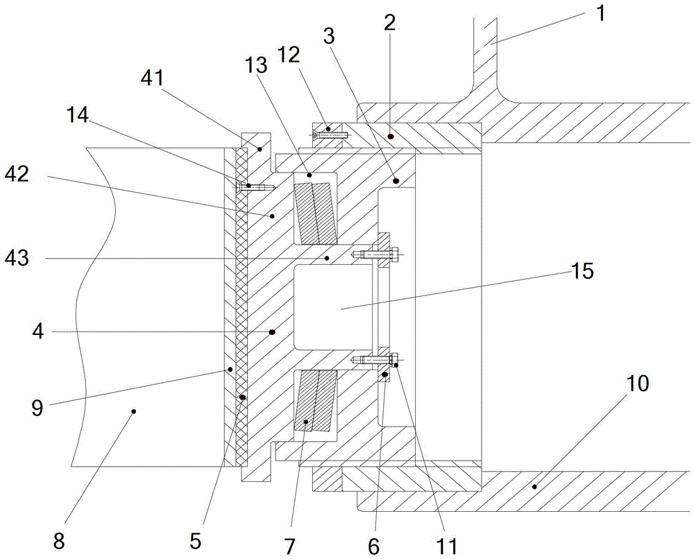
[0020] The following will combine figure 2 The ring beam connecting device provided by the present invention is described in detail, which is only a preferred embodiment of the present invention, and it can be considered that those skilled in the art can modify it within the scope of the content and spirit of the present invention according to the common knowledge and polish.

[0021] Please refer to figure 2 , this embodiment provides a ring beam connection device, including a support 1 and a connecting rod 10 perpendicular to the support 1 for connecting the ring beam 8, the support 1 is fixedly connected with other steel structures, the present The ring beam connection device provided in the embodiment also includes two positioning sleeves 3 with external threads on the outside and several butterfly springs 7, and the two positioning sleeves 3 are respectively movable with the two ends of the connecting rod 10 through their external threads. connected, the positioning s...


PUM


Abstract

The invention provides a ring beam connecting device comprising a support seat, a connecting rod which is vertical to the support seat and is used for connecting a ring beam, two positioning sleeves with external threads on the outer sides and a plurality of disc springs; the two positioning sleeves are respectively connected with both ends of the connecting rod movably through the external threads of the positioning sleeves; the positioning sleeves are connected with the ring beam through a guide rod; the disk springs are arranged between the guide rod and the positioning sleeves along the axial direction of the connecting rod; and the outer end surface of the guide rod is arranged on the outer side of the end surface of the connecting rod. According to the ring beam connecting device, an adjusting space is provided for the assembly and the disassembly of the ring beam through the movable connection between the positioning sleeves and the connecting rod; meanwhile, enough degree of freedom is provided for the ring beam along the axial direction of the connecting rod due to the disc springs; and finally, because the outer end surface of the guide rod is arranged on the outer side of the end surface of the connecting rod, the ring beam and the guide rod are not restricted on a vertical surface, and the stress along the vertical surface is released.

Description

technical field [0001] The invention relates to the field of building construction, in particular to a ring beam connecting device. Background technique [0002] At present, the curtain wall of the building is supported by a steel structure to withstand external forces such as weight, wind load, thermal expansion and contraction deformation, and earthquakes. At the steel structure nodes, there are various types of connection methods. In the past, the steel structure support nodes of the curtain wall used the form of mutual welding of rods. Under the action of external force and deformation, the rods could not be freely expanded and released. [0003] The ring beam is a kind of reinforced maintenance structure, which can improve the earthquake resistance of the building structure as a whole. The connection between the ring beam and the connection between the ring beam and other steel structures used to be realized by welding. In order to facilitate installation, a ring beam ...

Claims


Application Information

Patent Timeline
Patent Type & Authority Applications(China)
IPC IPC(8): E04B1/38E04B1/36
Inventor 孙继辉陈建民吴欣之毕伟麟吴金山沈新华罗魏凌
Owner SHANGHAI MECHANIZED CONSTR GRP
Why Eureka
Try Eureka