
Design method of a railway flexible guard rail device

A design method and technology for rail protection, applied in the field of rail transit, can solve the problems of difficult installation and limited installation space of rail protection devices, and achieve the effects of convenient installation, reduced maintenance workload and simple structure

Active Publication Date: 2020-06-09
CHINA RAILWAY ERYUAN ENG GRP CO LTD
View PDF5 Cites 0 Cited by
  • Summary
  • Abstract
  • Description
  • Claims
  • Application Information

AI Technical Summary

Problems solved by technology

[0002] In some high-risk track sections of existing railway tracks, guard rail devices need to be installed to prevent EMU wheels from derailing. Almost all devices are installed inside the railway rails, but as more and more equipment (such as electrical equipment, signal equipment, etc.) A guard rail device

Method used


Image

  • Design method of a railway flexible guard rail device
  • Design method of a railway flexible guard rail device
  • Design method of a railway flexible guard rail device

Examples


Embodiment 1

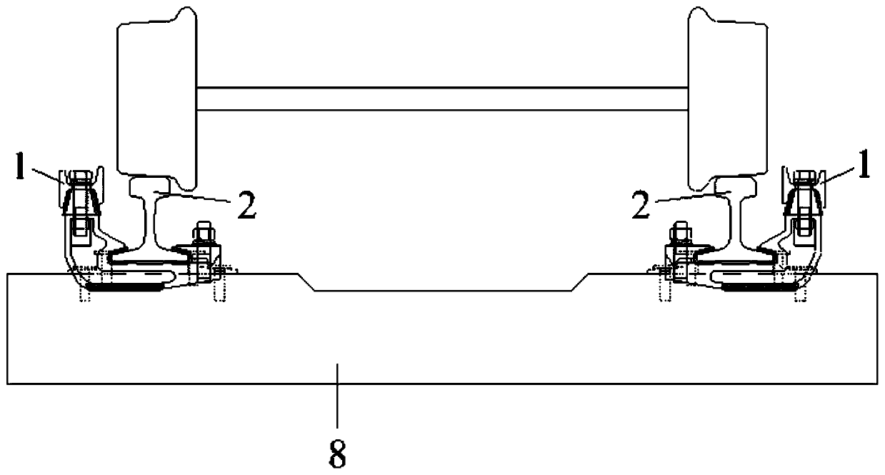
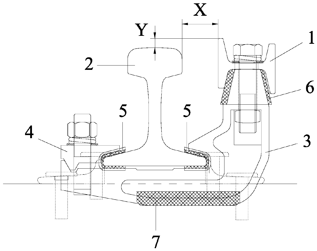
[0048] Such as Figure 1-6 As shown, the design method of a railway flexible guard rail device according to the present invention, the guard rail device includes a guard rail 1, and the guard rail 1 is located outside the rail 2, and the distance between the guard rail 1 and the rail 2 The distance X between and the distance Y between the top of the upper edge of the guard rail 1 higher than the top surface of the steel rail 2 are determined by the following equation:

[0049]

[0050]

[0051]

[0052]

[0053] Wherein, X is the design distance between the guard rail 1 and the rail 2, is the average value of the distance between the guard rail 1 and the rail 2, D is the rim width, L is the rail head width of the rail 2, d is the rim thickness, σ is the mean square error, N is the guarantee coefficient, Y is the design distance that the upper edge top of the guard rail 1 is higher than the top surface of the steel rail 2, H 1 is the effective height of the anti-...

Embodiment 2

[0057] Such as Figure 1-6 As shown, a railway flexible guard rail device according to the present invention is designed and manufactured using the design method of the railway flexible guard rail device as described in Embodiment 1.

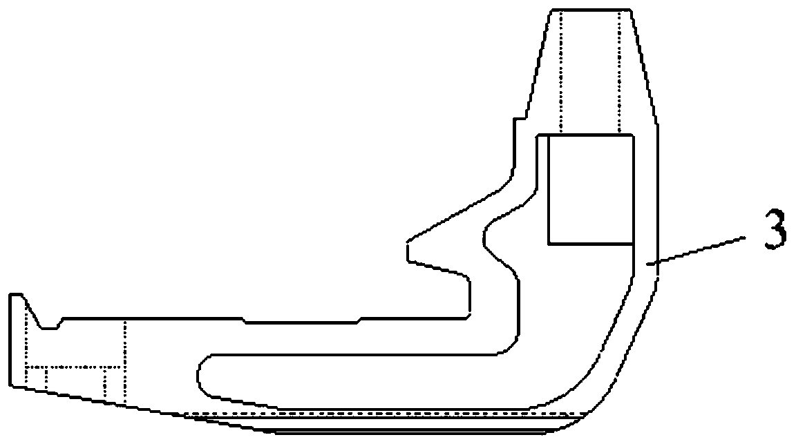
[0058] The guard rail device includes several supports 3 and several pressure plates 4, each of the supports 3 is a cantilever structure, each of the pressure plates 4 corresponds to one of the supports 3, and each of the pressure plates 4 is connected by bolts Corresponding to the support 3, the support 3 is clamped on the rail 2, between the support 3 and the rail 2, between the pressure plate 4 and the rail 2 are provided with The insulating sheet 5, the rail 2 is arranged on the sleeper 8.

[0059] The guard rail 1 is connected to the cantilever end of each support 3 by bolts, and a rubber sleeve 6 is arranged between the guard rail 1 and the support 3, such as Figure 5 As shown, the grade thicknesses of the front and rear working faces o...


PUM


Abstract

The invention discloses a design method of a railway flexible guardrail device. A guardrail is arranged on the outer side of a steel rail, the design method is initiated, equipment mounted on the inner side of the steel rail is avoided, the interval between the guardrail and the steel rail is X is the average value of the distance between the guardrail and the steel rail, and the average value iscalculated according to the wheel rail parameter rim width D, the steel rail head width L, and the wheel edge thickness d under the different rail areas and the different conditions; meanwhile, the mean square error of the principle of statistics is adopted for analyzing out deviation, a specific flexible guardrail device is used for laying a section, different guarantee coefficients N are selected for precisely calculating the design value of the V value, and derail of wheels of the D-series high-speed train can be effectively prevented.

Description

technical field [0001] The invention relates to the field of rail transportation, in particular to a railway flexible guard rail device and a design method thereof. Background technique [0002] In some high-risk track sections of existing railway tracks, guard rail devices need to be installed to prevent EMU wheels from derailing. Almost all devices are installed inside the railway rails, but as more and more equipment (such as electrical equipment, signal equipment, etc.) A guard rail device. Contents of the invention [0003] The purpose of the present invention is to overcome the existing problems in the prior art, that is, the existing guard rail devices are almost all arranged on the inner side of the railway rail, but as more and more equipment is installed on the inner side of the rail, the guard rail device on the inner side of the rail The installation space is limited, and even the above-mentioned shortcomings that are difficult to install, provide a railway f...

Claims


Application Information

Patent Timeline
Patent Type & Authority Patents(China)
IPC IPC(8): E01B5/18
Inventor 韩义涛田春香李粮余李大东潘自立张凯李保友莫宏愿
Owner CHINA RAILWAY ERYUAN ENG GRP CO LTD
Learn More