A device for separating cutting fluid from iron filings

A separation device and chip fluid technology, applied in the field of mechanical processing, can solve the problems of incomplete separation of iron filings and chip fluid, low efficiency of chip fluid recovery, etc., and achieve the effect of ingenious structure, high efficiency, thorough and efficient separation

Active Publication Date: 2019-09-24
TIANJIN UNIV OF TECH & EDUCATION TEACHER DEV CENT OF CHINA VOCATIONAL TRAINING & GUIDANCE
View PDF6 Cites 0 Cited by
  • Summary
  • Abstract
  • Description
  • Claims
  • Application Information

AI Technical Summary

Problems solved by technology

[0004] In view of the above situation, in order to overcome the defects of the prior art, the purpose of the present invention is to provide a separation device for cutting fluid in iron filings, which effectively solves the incomplete separation of iron filings and cutting fluid in the prior art and the low recovery efficiency of cutting fluid. And other issues

Method used


Image

  • A device for separating cutting fluid from iron filings
  • A device for separating cutting fluid from iron filings
  • A device for separating cutting fluid from iron filings

Examples


Embodiment Construction

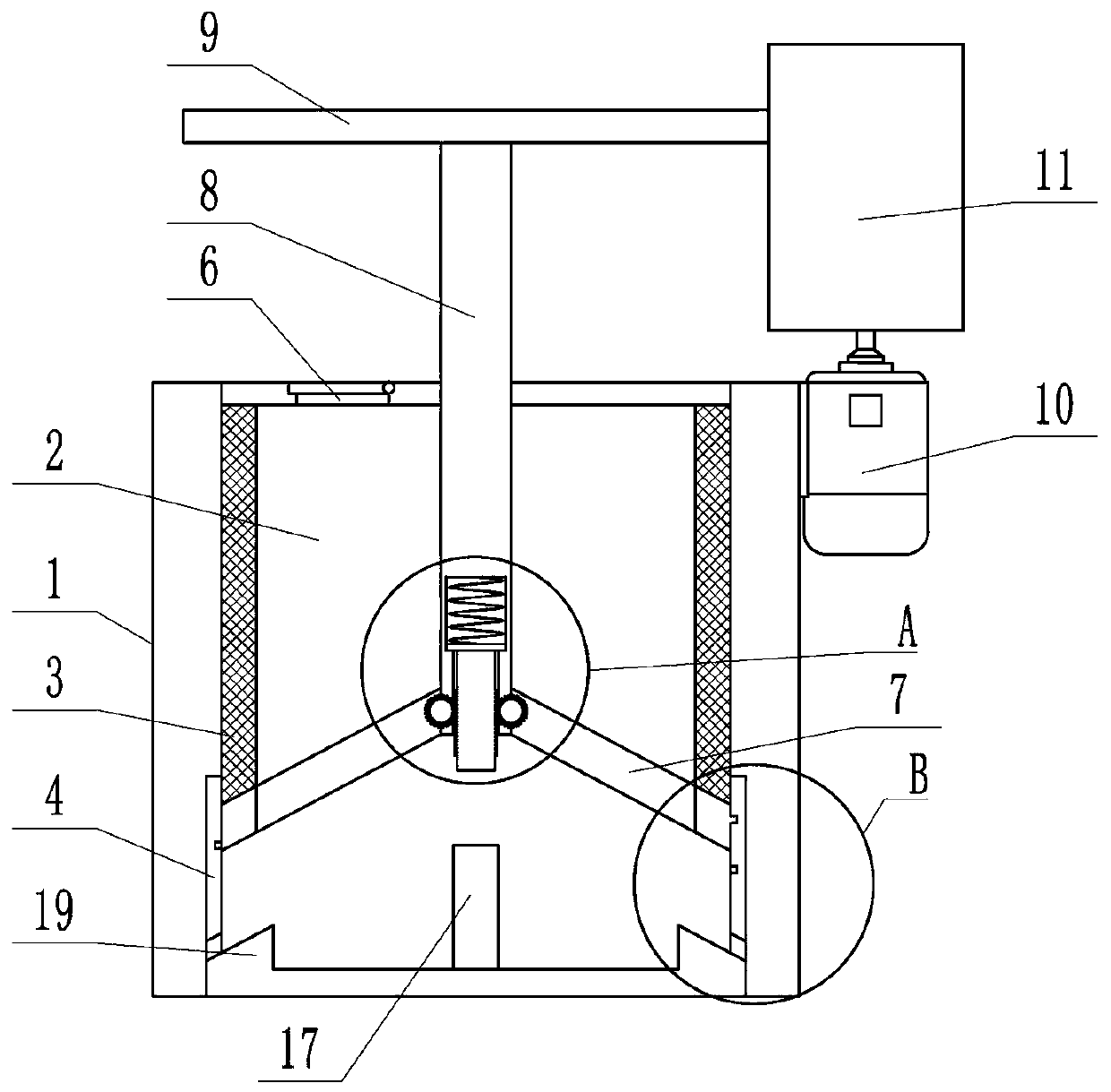
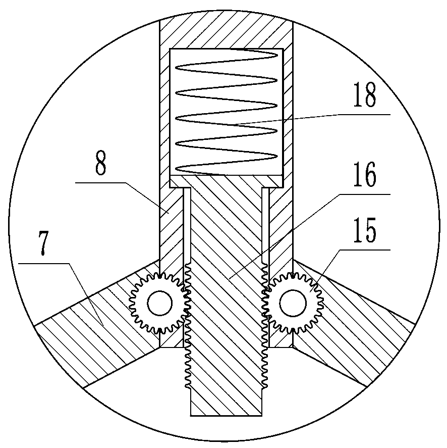
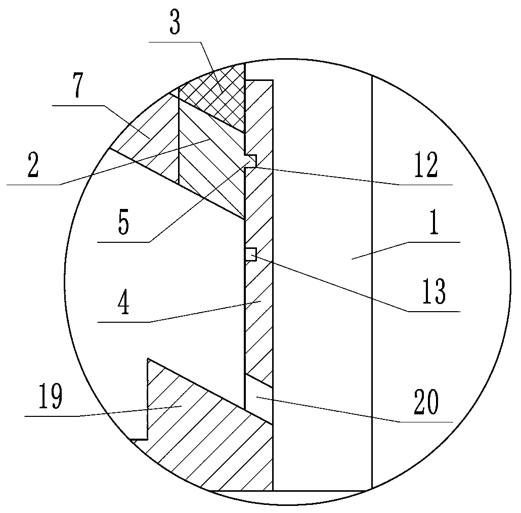
[0014] The following is attached Figure 1 to Figure 7 The specific implementation manner of the present invention will be described in further detail.

[0015] Depend on Figure 1 to Figure 7 It can be known that a separation device for cutting liquid in iron filings includes a liquid collecting bucket 1 and a dumping bucket 2, the spinning bucket 2 is movable and fixed inside the liquid collecting bucket 1, the outer wall of the spinning bucket 2 is a filter screen 3, and the inner bottom of the liquid collecting bucket 1 There is a fixed plate 4 positioned at the outer side of the bucket 2, the fixed plate 4 is provided with a spiral groove, and the positioning rod 5 inserted into the spiral groove protrudes from the bucket 2, and the positioning rod 5 slides in the spiral groove to make the bucket 2 in the spiral groove. The liquid collecting barrel 1 rotates and vibrates up and down. The upper part of the throwing barrel 2 is provided with a feed port 6, and the bottom o...


PUM


Abstract

The invention provides a separation device for chip liquid in iron filings. The problems that in the prior art, separation of the iron filings and the chip liquid is incomplete, and the recovery efficiency of the chip liquid is low are effectively solved. The separation device comprises a liquid collecting barrel and a swinging barrel, the swinging barrel is movably fixed into the liquid collecting barrel, a first filter screen is arranged on the outer wall of the swinging barrel, a fixing plate located on the outer side of the swinging barrel is arranged at the bottom of the inner side of theliquid collecting barrel, a spiral groove is formed in the fixing plate, a positioning rod inserted into the spiral groove extends out of the swinging barrel, the positioning rod slides in the spiralgroove to make the swinging barrel rotate in the liquid collecting barrel and vibrate up and down, a feeding port is formed in the upper part of the swinging barrel, a plurality of bottom plates arearranged at the bottom of the swinging barrel, when the swinging barrel rotates forwards, the swinging barrel is in the state of separating the chip liquid, and when the swinging barrel rotates reversely, the multiple bottom plates are rotatably opened to complete discharging of the iron filings. According to the separation device for the chip liquid in the iron filings, the structure is ingenious, the chip liquid is separated from the iron filings in a mode of spinning, separation is more thorough and efficient, secondary separation is not required, and the efficiency is higher.

Description

technical field [0001] The invention relates to the technical field of mechanical processing, in particular to a separation device for cutting liquid in iron filings. Background technique [0002] At present, most factories in China do not pay enough attention to the treatment of cutting fluid containing waste chips. The situation of waste chips being piled up in the open air and cutting fluid being thrown everywhere is becoming more and more serious. [0003] At this stage, most factories have large open-air waste dumps to store a large amount of waste. The workers transport the waste from the machine tool to the stacking site by the waste pick-up trolley and pour them in, and then load them in a unified manner. shipped away. In the process of transporting waste chips, due to the large amount of cutting fluid contained in the untreated waste chips and the incomplete sealing of the trolley, which is easy to leak, it will cause oil leakage and iron filings during the handlin...

Claims


Application Information

Patent Timeline
Patent Type & Authority Patents(China)
IPC IPC(8): B01D33/29B01D33/76
Inventor 靳刚张开飞李占杰韩建鑫崔良玉
Owner TIANJIN UNIV OF TECH & EDUCATION TEACHER DEV CENT OF CHINA VOCATIONAL TRAINING & GUIDANCE
Why Eureka
Try Eureka