Electronic switch lock

An electronic switch and lock body technology, which is applied in the locking part of the electronic switch lock, can solve the problems of pervasiveness, poor anti-theft effect of two-wheeled and three-wheeled motor vehicles, etc., and achieve the goal of preventing carelessness, simplifying operation, and compact overall structure Effect

Inactive Publication Date: 2019-06-14
江苏圣龙智能科技有限公司
View PDF0 Cites 1 Cited by
  • Summary
  • Abstract
  • Description
  • Claims
  • Application Information

AI Technical Summary

Problems solved by technology

[0002] In order to prevent motorcycles, battery cars and other two-wheeled and three-wheeled motor vehicles from being stolen, people usually use locks to lock the handlebars or wheels of such vehicles. As for craftsmanship, most of the suspects in this area have been engaged in motor vehicle repairs, are professional in unlocking technology, are familiar with the structure of vehicles, and are proficient in theft methods. The use of bolt cutters, screwdrivers, cross lock breaking tools, multi-model motorcycle keys, motorcycle ignition locks and other crime tools makes the anti-theft effect of motorcycles, battery cars and other two-wheeled and three-wheeled motor vehicles poor
[0003] In the more advanced keyless start solutions on the market, it is often necessary to remotely lock the vehicle with a wireless key when locking the car, and then lock the car through an electronic switch. However, market research has found that most customers will Because of carelessness or other reasons, forget to lock the car with the key, which leads to opportunities for criminals to take advantage of. Therefore, a convenient and fast anti-theft electronic switch lock has a great market.

Method used


Image

  • Electronic switch lock
  • Electronic switch lock
  • Electronic switch lock

Examples


Embodiment Construction

[0033] In order to deepen the understanding of the present invention, the present invention will be further described below in conjunction with the embodiments and accompanying drawings. The embodiments are only used to explain the present invention and do not constitute a limitation to the protection scope of the present invention.

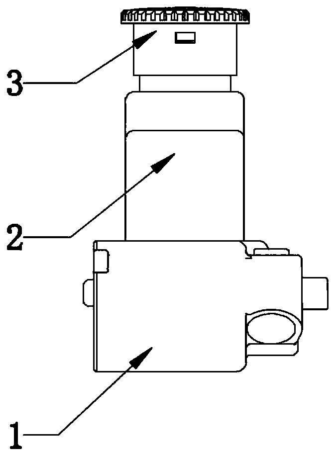
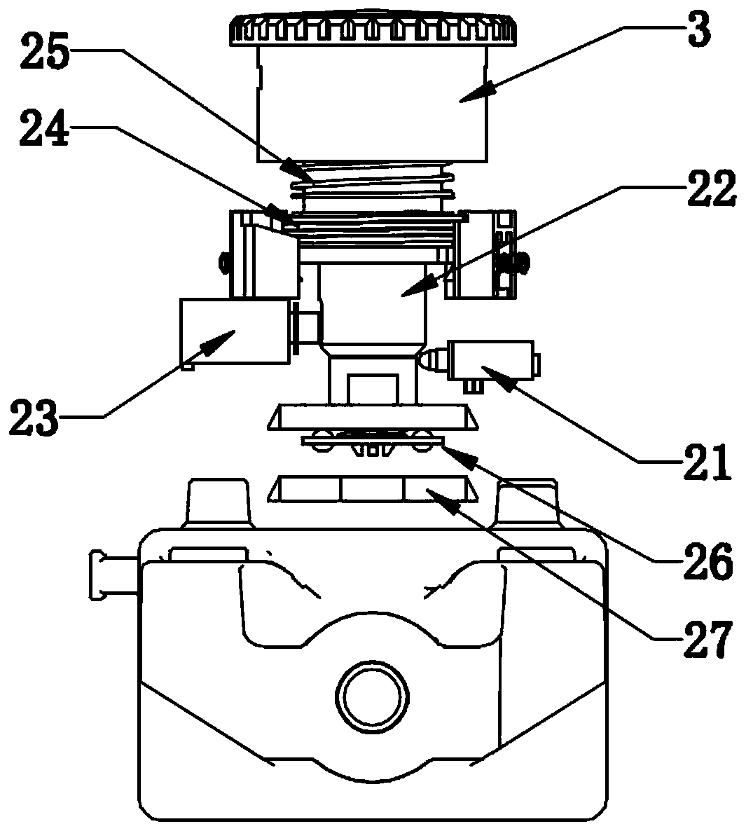
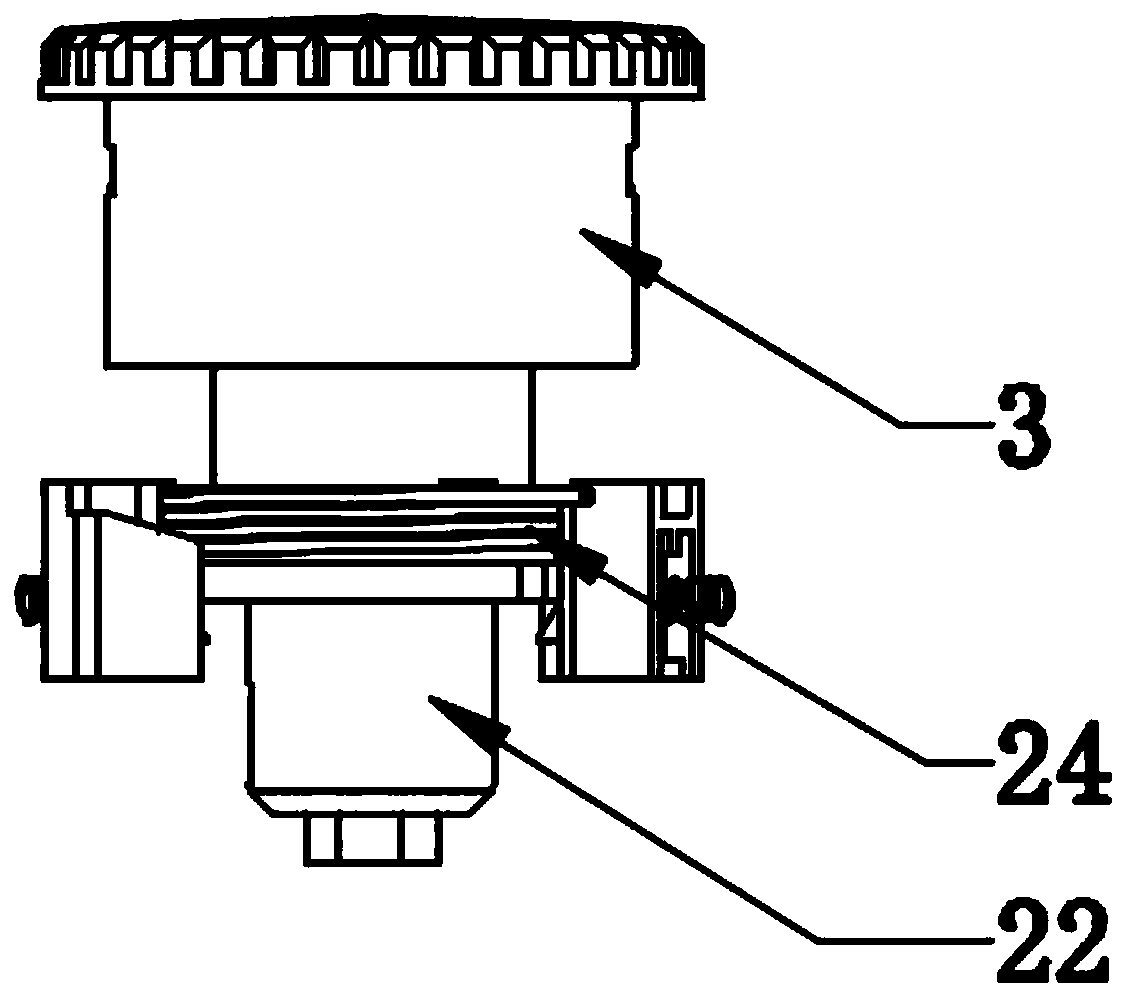
[0034] Such as figure 1 As shown, an electronic switch lock includes a tap lock part 1 and a lock body 2; a rotating shaft 22 is connected in the central hole of the lock body 2, and an activation switch 21 and an activation switch 21 are also connected on the side wall of the central hole of the lock body 2. Electromagnetic valve 23; the rotating shaft 22 is a stepped shaft, and the top of the rotating shaft 22 is connected to the rotating cover 3, and the rotating cover 3 is connected to the lock body 2 through a return spring 25, and the shoulder part of the step shaft is The transition arc, the shaft body part of the stepped shaft is provided...


PUM


Abstract

The invention relates to an electronic switch lock. The electronic switch lock comprises a lock body, wherein a rotary shaft which is a step shaft is connected in a center hole of the lock body; the top of the rotary shaft is connected with a rotary cover; the rotary cover is connected to the lock body through a return spring; the shaft shoulder part of the step shaft is a transition circular arc;a key slot is formed in the shaft body part of the step shaft; the head part of an activation switch abuts against the side surface of the transition circular arc; the head of a solenoid valve is a lug boss which is embedded into the key slot, and can slide up and down in the key slot; a torsion spring is further connected on the rotary shaft; the shaft body of the rotary shaft is further connected with a plurality of tongue-shaped outer flanges in an outwards bulged mode, and a notch is formed between adjacent tongue-shaped outer flanges; and a plurality of blocking holes and limiting baffleblocks are further connected on the lock body. The electronic switch lock is quick in operation, is friendly in operation way, and can greatly reduce conditions, caused by carelessness of an operator, which can be used by a lawbreaker.

Description

technical field [0001] The invention relates to an electronic switch lock, in particular to a locking part of the electronic switch lock. Background technique [0002] In order to prevent motorcycles, battery cars and other two-wheeled and three-wheeled motor vehicles from being stolen, people usually use locks to lock the handlebars or wheels of such vehicles. As for craftsmanship, most of the suspects in this area have been engaged in motor vehicle repairs, are professional in unlocking technology, are familiar with the structure of vehicles, and are proficient in theft methods. The use of bolt cutters, screwdrivers, cross lock breaking tools, multi-model motorcycle keys, motorcycle ignition locks and other crime tools makes the anti-theft effect of motorcycles, battery cars and other two-wheeled and three-wheeled motor vehicles poor. [0003] In the more advanced keyless start solutions on the market, it is often necessary to remotely lock the vehicle with a wireless key...

Claims


Application Information

Patent Timeline
Patent Type & Authority Applications(China)
IPC IPC(8): E05B71/00E05B47/00E05B15/00E05B15/04
Inventor 高华
Owner 江苏圣龙智能科技有限公司
Why Eureka
Try Eureka