Shield tunnel duct piece structure and shield tunnel lining
A shield tunnel segment and segment technology, which is applied in tunnel lining, tunnel, wellbore lining, etc., can solve the problems of unsatisfactory control effect of surrounding environment, not equipped with synchronous grouting pipeline, and the effect cannot be optimized, etc. To achieve the effect of simple and practical structure, avoiding the concentration of grouting area and reducing the impact
- Summary
- Abstract
- Description
- Claims
- Application Information
AI Technical Summary
Problems solved by technology
Method used
Image
Examples
Embodiment 1
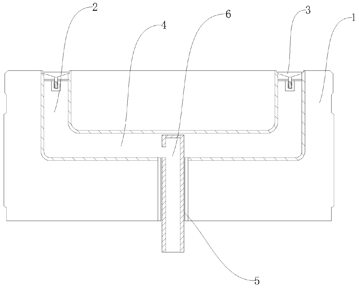
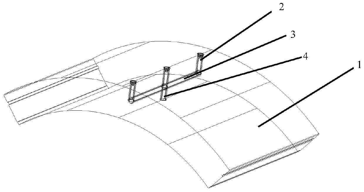
[0024] Embodiment 1: As shown in the figure, a shield tunnel segment structure includes a segment body 1 and at least one set of grouting mechanisms arranged in the segment body 1, and each set of grouting mechanisms includes a plurality of front and rear The grouting pipes 2 distributed at intervals, the upper ends of the multiple grouting pipes 2 all extend to the outer surface of the segment body 1, and the upper ends of the multiple grouting pipes 2 are fixed with check valves 3, and the multiple grouting pipes 2 The lower end of the second connecting pipe 5 communicates with the first connecting pipe 4 distributed horizontally, and the second connecting pipe 5 communicates with the lower end of the second connecting pipe 5 extending to the inner surface of the segment body 1 .
Embodiment 2
[0025] Embodiment 2: As shown in the figure, a shield tunnel segment structure includes a segment body 1 and at least one set of grouting mechanisms arranged in the segment body 1, and each set of grouting mechanisms includes a plurality of front and rear The grouting pipes 2 distributed at intervals, the upper ends of the multiple grouting pipes 2 all extend to the outer surface of the segment body 1, and the upper ends of the multiple grouting pipes 2 are fixed with check valves 3, and the multiple grouting pipes 2 The lower end of the second connecting pipe 5 communicates with the first connecting pipe 4 distributed horizontally, and the second connecting pipe 5 communicates with the lower end of the second connecting pipe 5 extending to the inner surface of the segment body 1 .
[0026] In this embodiment, there are two grouting pipes 2 , and the second connecting pipe 5 is located at the midpoint of the line connecting the two grouting pipes 2 .
[0027] In this embodimen...
Embodiment 3
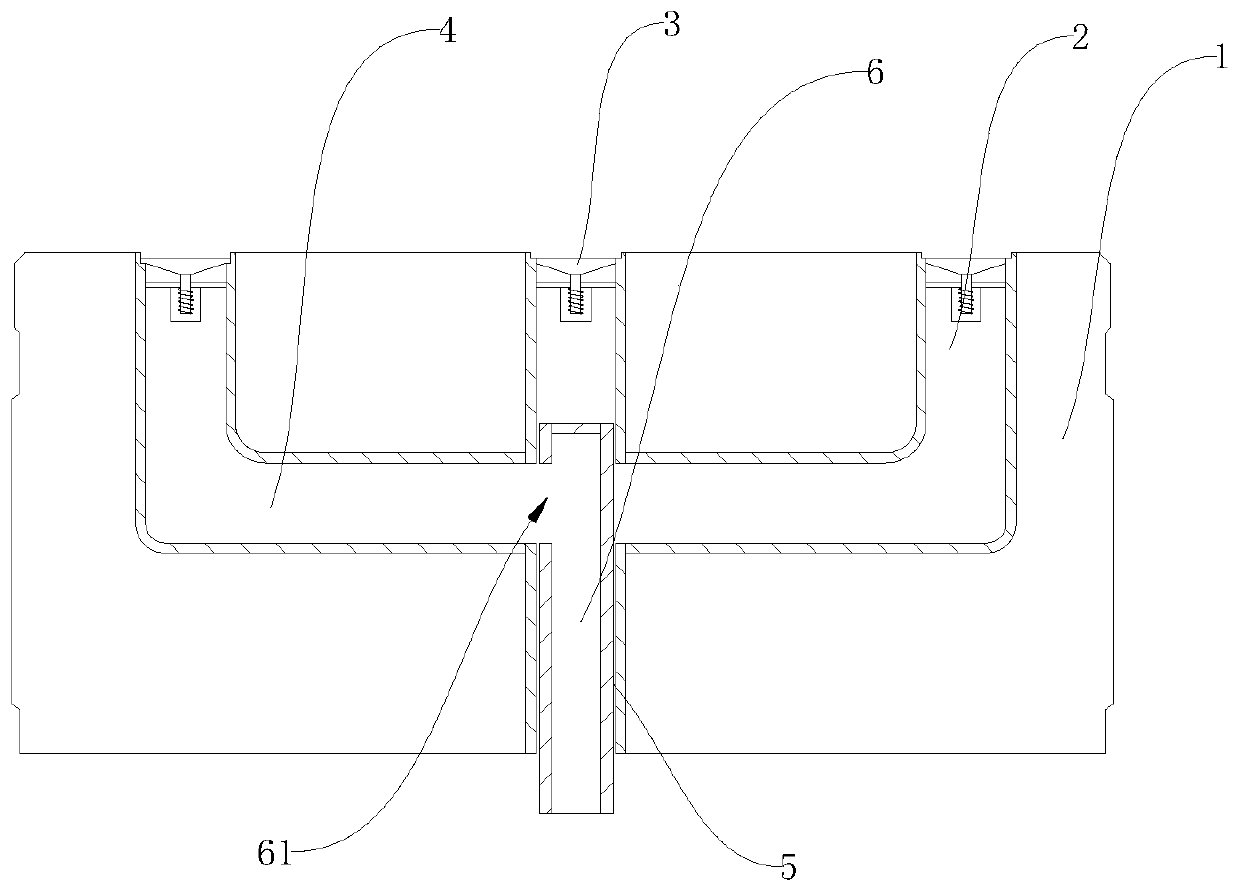
[0029] Embodiment 3: As shown in the figure, a shield tunnel segment structure includes a segment body 1 and at least one set of grouting mechanisms arranged in the segment body 1, and each set of grouting mechanisms includes a plurality of front and rear The grouting pipes 2 distributed at intervals, the upper ends of the multiple grouting pipes 2 all extend to the outer surface of the segment body 1, and the upper ends of the multiple grouting pipes 2 are fixed with check valves 3, and the multiple grouting pipes 2 The lower end of the second connecting pipe 5 communicates with the first connecting pipe 4 distributed horizontally, and the second connecting pipe 5 communicates with the lower end of the second connecting pipe 5 extending to the inner surface of the segment body 1 .
[0030] In this embodiment, there are three grouting pipes 2 , and the second connecting pipe 5 is located directly below the middle grouting pipe 2 .
[0031] In this embodiment, the shield tunnel...
PUM
| Property | Measurement | Unit |
|---|---|---|
| Diameter | aaaaa | aaaaa |
Abstract
Description
Claims
Application Information
 - R&D Engineer
- R&D Manager
- IP Professional
- Industry Leading Data Capabilities
- Powerful AI technology
- Patent DNA Extraction
Browse by: Latest US Patents, China's latest patents, Technical Efficacy Thesaurus, Application Domain, Technology Topic, Popular Technical Reports.
© 2024 PatSnap. All rights reserved.Legal|Privacy policy|Modern Slavery Act Transparency Statement|Sitemap|About US| Contact US: help@patsnap.com


