Remote system for PLC equipment debugging and method thereof

A technology of remote systems and equipment, applied in the direction of program control and electrical program control in sequence/logic controllers, can solve problems such as difficulties, and achieve the effect of improving data stability and development efficiency

Inactive Publication Date: 2019-06-14
ZHEJIANG GENO ELECTRICAL
View PDF6 Cites 11 Cited by
  • Summary
  • Abstract
  • Description
  • Claims
  • Application Information

AI Technical Summary

Problems solved by technology

[0006] The technical problem solved by the present invention is to provide a remote system and method for debugging PLC equipment based on network communication technology for the above-mentioned existing technical defects, which are used to replace the traditional debugging technology and solve the difficulty of equipment wiring and data The problem of poor stability improves the development efficiency of users

Method used


Image

  • Remote system for PLC equipment debugging and method thereof
  • Remote system for PLC equipment debugging and method thereof
  • Remote system for PLC equipment debugging and method thereof

Examples


Embodiment Construction

[0020] In order to make the purpose, technical solutions and beneficial effects of the present invention more clear, the present invention will be further described in detail below in conjunction with the accompanying drawings and specific embodiments.

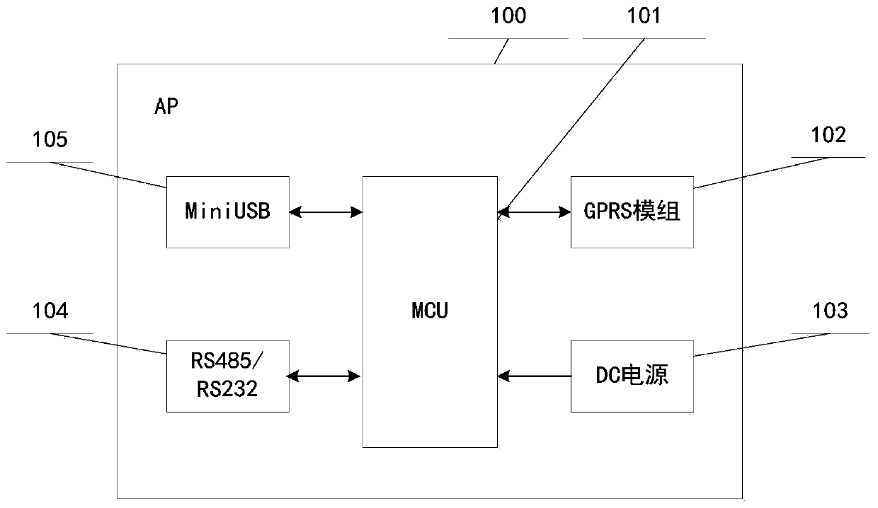
[0021] figure 1 A schematic diagram of the hardware interface of the AP device 100 that facilitates the use of the present invention is shown. The interfaces of the AP include: a micro control unit (MCU) 101 , a GPRS module 102 , a DC power supply interface 103 , an RS485 / RS232 interface 104 , and a MiniUSB interface 105 . Among them, the MCU is the control center of the equipment, the GPRS module is the network data sending and receiving part, the MiniUSB interface is the parameter configuration interface, and the RS485 / RS232 interface is connected to the PLC equipment through wires.

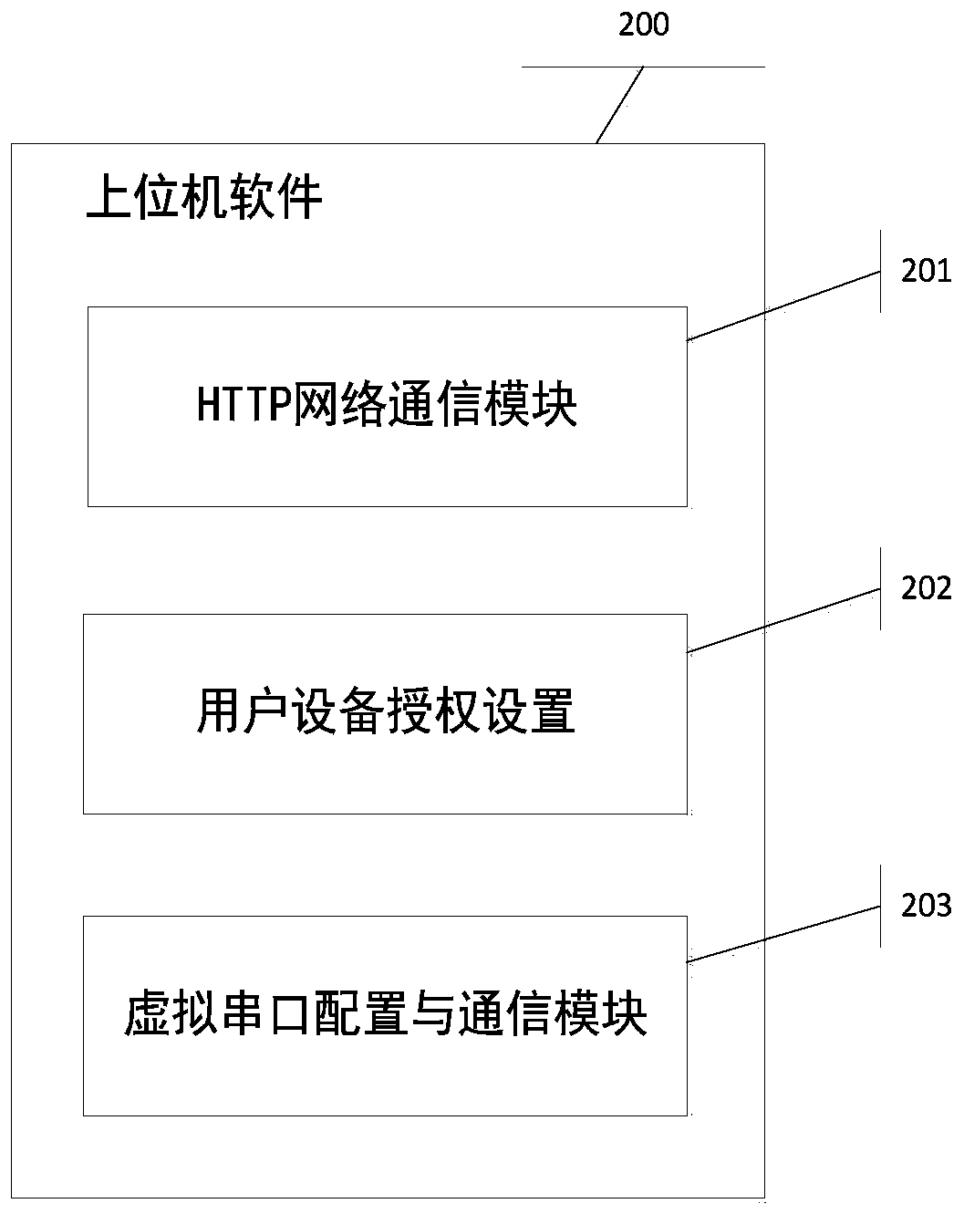
[0022] figure 2 A functional schematic diagram of the host computer software 200 that facilitates the use of the present invention is shown...


PUM


Abstract

The invention discloses a remote system for PLC equipment debugging and a method thereof. The system consists of virtual serial port bridging software, a background server and an industrial gateway concentrator, wherein the industrial gateway concentrator equipment on a physical connection line is connected with traditional PLC equipment; the virtual serial port bridging software is connected withIDE software of a corresponding PLC through a virtual serial port; a transmission layer protocol central server is connected with the virtual serial port bridging software through an HTTP protocol and connected with the industrial gateway concentrator equipment through an MQTT protocol; the industrial gateway concentrator equipment is connected with the PLC through the physical connection line and sends information in a transparent transmission line; and the virtual serial port bridging software sends information in the same transparent transmission line. According to the system and the method, the users do not need to change the original programs and can remotely debug the PLC equipment without being limited by territories, so that the operation is convenient and efficient.

Description

technical field [0001] The invention relates to network communication and serial port communication, in particular to a remote system and method for debugging PLC equipment based on network communication technology. Background technique [0002] Regarding the PLC remote debugging technology, the commonly used method in the prior art is the PLC debugging through the telephone line, which is slow and expensive. Or through the router to build a virtual private network for PLC debugging, the module is complex and subject to conditions. The traditional method has the following disadvantages: [0003] First, environmental and geographical restrictions. Wiring is difficult for some products, and the traditional method needs to introduce telephone lines or Ethernet lines for network communication, which is not suitable for this part of products; [0004] Second, the data stability is poor. Some products can only transmit data, and cannot maintain and resend data packet loss and ...

Claims


Application Information

Patent Timeline
Patent Type & Authority Applications(China)
IPC IPC(8): G05B19/05
Inventor 孙永贵舒云平郑小锋
Owner ZHEJIANG GENO ELECTRICAL
Why Eureka
Try Eureka