Analog circuit experimental equipment and method of determining required electronic components thereof

A technology of electronic components and experimental equipment, which is applied in the field of analog circuit experimental equipment and the determination of the types and quantities of electronic components required, which can solve problems such as unfavorable students' innovative thinking and application, poor scalability of experimental content, and inability to be used alone. , to achieve the effect of promoting the combination of inside and outside the classroom, a good practice training platform, and the cultivation of application ability.

Pending Publication Date: 2018-01-19
YIBIN UNIV
View PDF3 Cites 4 Cited by
  • Summary
  • Abstract
  • Description
  • Claims
  • Application Information

AI Technical Summary

Problems solved by technology

[0015] The purpose of the present invention is to provide a method for determining analog circuit experimental equipment and its required electronic components, so as to solve the problem of existing analog circuit course experimental teaching equipment with fixed circuit structure, poor expansibility of experimental content, and the establishment of comprehensive d

Method used


Image

  • Analog circuit experimental equipment and method of determining required electronic components thereof
  • Analog circuit experimental equipment and method of determining required electronic components thereof
  • Analog circuit experimental equipment and method of determining required electronic components thereof

Examples


Embodiment 1

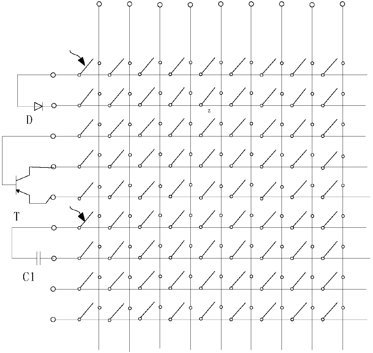
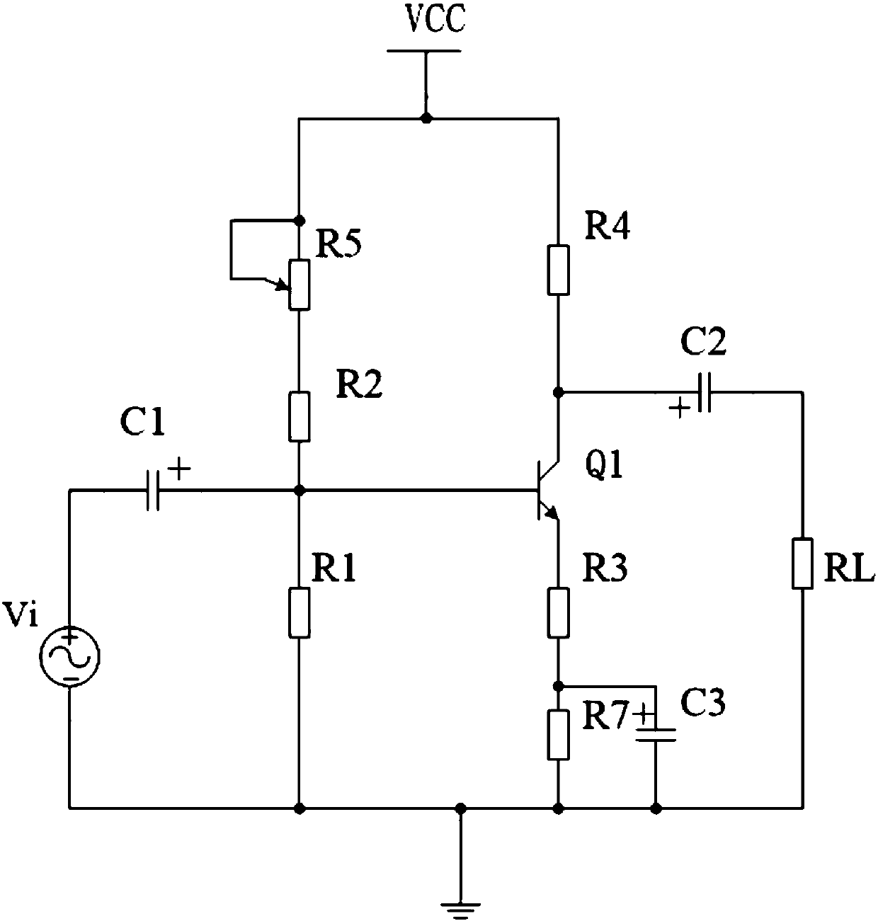
[0058] right image 3 For the single-tube amplifier shown, the connection relationship of the jumper matrix is ​​as follows Figure 4 As shown in the figure, the black arrow indicates the connection relationship. In order to reduce the device, image 3 The resistance in the Figure 4 should be a potentiometer, in order to facilitate understanding, the Figure 4 The potentiometer symbol that realizes the function of fixed resistance is drawn as a fixed resistance symbol. Figure 5Among the two sine waves shown, the one with a small amplitude is the waveform of the circuit input voltage Vi, and the one with a large amplitude is the waveform of the voltage signal on the output load RL. It can be seen from the waveform amplitude that the normal experimental function can be completed with the experimental equipment designed by this patent.

[0059] in, image 3 and Figure 4 R1-R5, R7, and RL in the diagram represent resistors, C1-C3 represent capacitors, Q1 represents a tri...

Embodiment 2

[0061] right Figure 6 In the integrated circuit shown, the connection relationship of the jumper matrix is ​​as follows Figure 7 As shown in the figure, the black arrow indicates the connection relationship. Similarly, in order to reduce the number of components, Figure 5 The resistors and capacitors in the Figure 6 should be potentiometers, adjustable capacitors, in order to facilitate understanding, the Figure 6 The symbol of the potentiometer that realizes the function of fixed resistance is drawn as a symbol of fixed resistance, and the symbol of adjustable capacitor is drawn as a symbol of fixed capacitance. Figure 8 The square and triangle waves shown correspond to the circuit input and output signals, respectively. From the experimental results, it can be seen that the normal experimental function can be completed with the experimental equipment designed by this patent.

[0062] in, Figure 6 and Figure 7 R1-R2 in it represents resistance, Vi represents si...


PUM


Abstract

The invention provides analog circuit experimental equipment and a method of determining required electronic components thereof. The equipment includes a jumper module, an experimental electronic component plug-in module, a programmable sine signal generator, a programmable power supply, and a numerical control acquisition module; the jumper module consists of multiple row conductors, multiple column conductors and multiple jumper switches; the multiple jumper switches are arranged in a matrix mode, a first pin of the jumper switches in each row of the matrix is connected with one row conductor, a second pin of the jumper switches in each row of the matrix is connected to one column conductor, and when all jumper switches are in a disconnected state, each row of conductors and each columnof conductors are in a mutually insulated non-conductive state; the row conductors and the column conductors are connected with the pins of the experimental electronic component plug-in module correspondingly one to one. According to the analog circuit experimental equipment, the jumper module is applied to solve the problems that the wiring of a universal circuit board is difficult and error-prone and a device can be mistakenly burned.

Description

technical field [0001] The invention relates to the technical field of teaching experiment equipment, in particular to an analog circuit experiment equipment and a method for determining types and quantities of required electronic components. Background technique [0002] As a basic core course of electronics major, analog circuit has strong theory and practice, and plays a very important role in the course system. Because there are many types of devices in analog circuits, and there are infinitely many continuous states of parameters and signals, the theoretical knowledge is complex. Compared with digital circuits, analog circuits are more difficult to learn, and it is difficult to achieve an organic combination of theory and practice. It is of great significance to develop effective analog circuit experimental equipment, promote the combination of theory and practice for students, and help students apply the theoretical knowledge of analog circuits to engineering practice....

Claims


Application Information

Patent Timeline
IPC IPC(8): G09B23/18
Inventor 周启忠张超洋徐娟官国仕
Owner YIBIN UNIV
Why Eureka
Try Eureka