Socket

A socket and tooth technology, which is applied to electrical components, coupling devices, circuits, etc., can solve the problem of the singleness of the connector installation direction, and achieve the effects of simple and reliable structure, low cost and low manufacturing difficulty.

Pending Publication Date: 2019-06-14
苏州正北连接技术有限公司
View PDF1 Cites 0 Cited by
  • Summary
  • Abstract
  • Description
  • Claims
  • Application Information

AI Technical Summary

Problems solved by technology

[0003] The application provides a socket, which realizes the rotation and locking functions of the connector at any angle, and solves the problem of the single installation direction of the existing connector

Method used


Image

  • Socket
  • Socket
  • Socket

Examples


Embodiment Construction

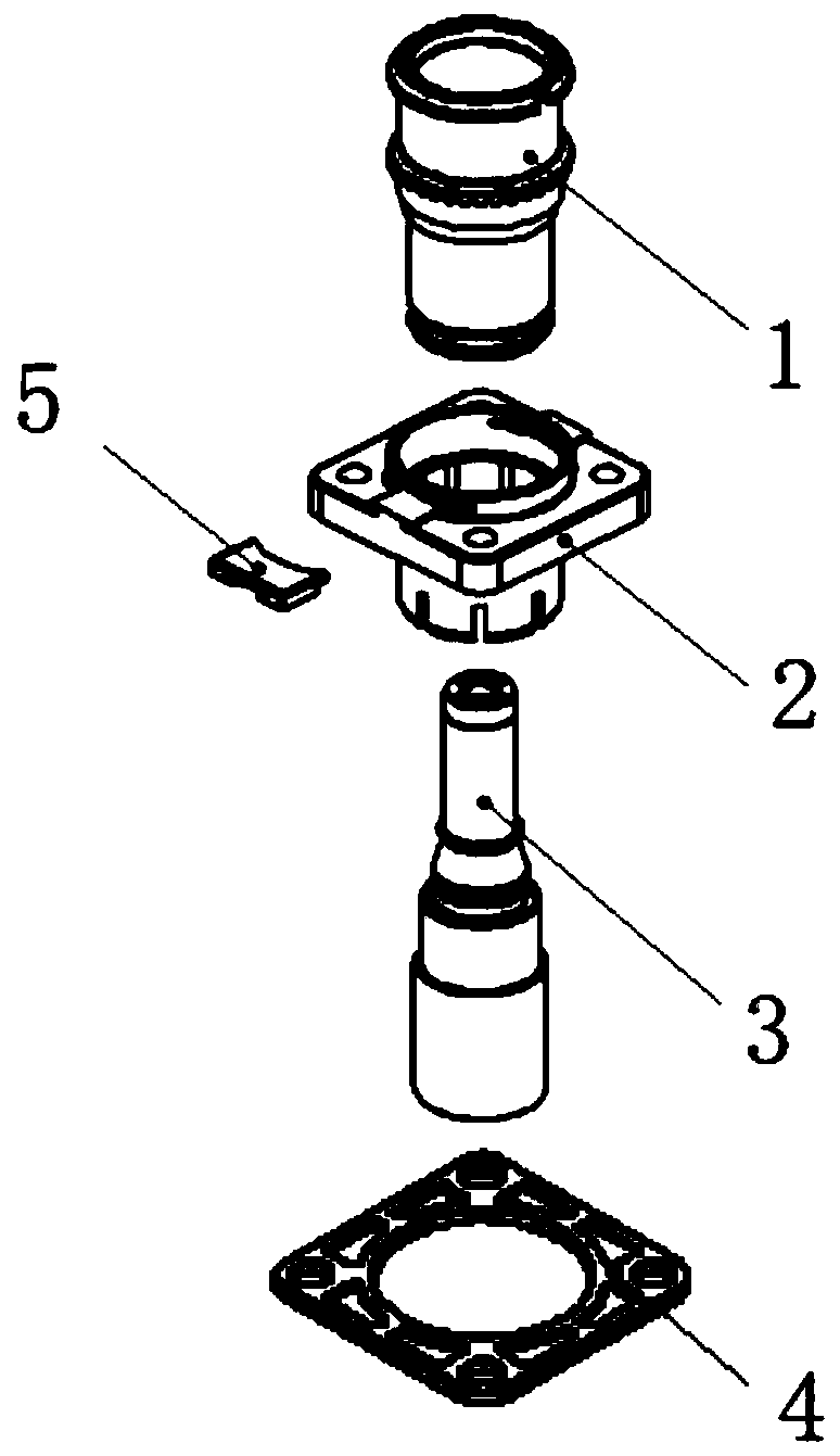
[0025] First, refer to figure 1 , the socket of this application mainly includes three main structures: socket rotating shell 1, socket shell 2 and socket conductor 3; Figure 4 The socket rotating shell has a big end and a small end, the small end of the socket rotating shell runs through the socket shell, and the big end of the socket rotating shell is blocked and fixed by the socket shell. The socket conductor is inserted into the socket rotary shell from the small end of the socket rotary shell, and its conductive end is flush with the big end of the socket rotary shell; a sealing ring 4 is arranged between the socket conductor 3 and the socket shell 2 .

[0026] In order to achieve rotation locking, the present application relates to a two-stage locking structure.

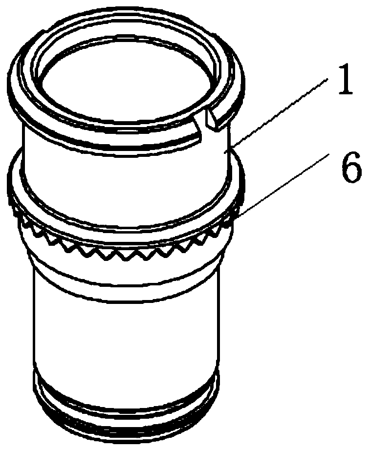
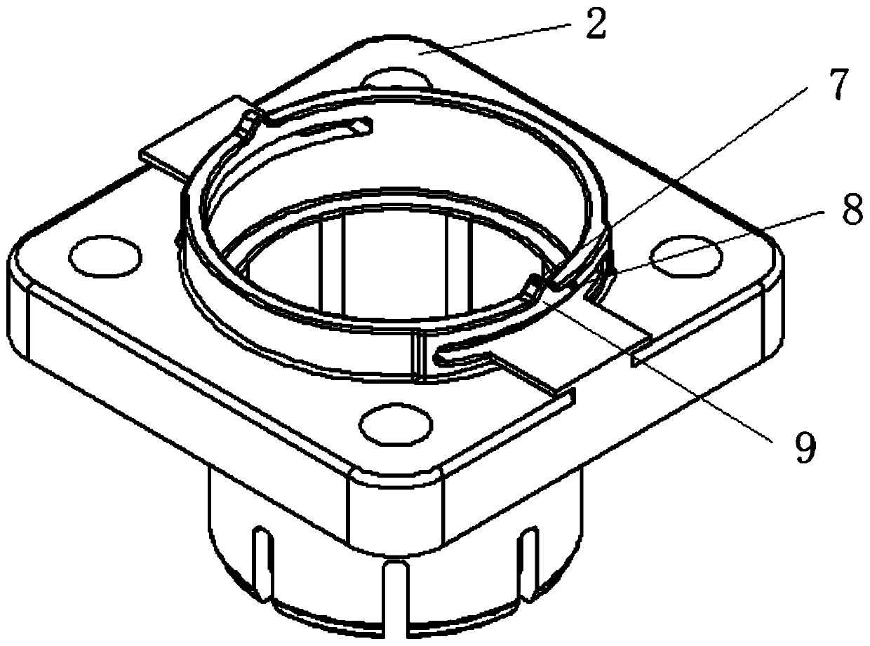
[0027] Such as figure 2 shown with image 3 As shown, the first-level locking structure is mainly composed of a number of first locking teeth 6 arranged on an outer circumference of the socket rotating she...


PUM


Abstract

The invention belongs to the field of connectors and relates to a socket. The socket comprises a socket shell and a socket rotating shell, wherein the socket rotating shell penetrates through the socket shell and can rotate relative to the socket shell; a plurality of first clamping teeth are distributed on the outer surface of the socket rotating shell along a circumferential line of the socket rotating shell, and a first clamping slot is formed between every two adjacent first clamping teeth; the socket shell is provided with elastic force arms in the rotating path of the first clamping teeth, the elastic force arms partially protrude towards the first clamping slots to form second clamping teeth cooperating with the first clamping slots, and the second clamping teeth and the first clamping slots are in clearance fit to form first-level rotary locking; and meanwhile, elastic lock holes are formed between the elastic force arms and surfaces, where the elastic force arms are arranged,of the socket shell. Through the socket, the rotating and locking functions of a connector at an arbitrary angle are achieved, and the problem that an existing connector has a single installation direction is solved.

Description

technical field [0001] The invention belongs to the field of connectors and relates to a socket which can be rotated arbitrarily and has a locking function. Background technique [0002] With the rapid development of new energy technology, the requirements for connectors are getting higher and higher. Lightweight requirements put forward less and less space for connector arrangement. It is necessary to realize the basic functional requirements and minimize the space occupied by the connector, which makes the connector structure very complicated. And the singleness of the installation direction of the connector limits the convenience of the overall wiring. In order to realize the multi-function of the connector, the existing connector has a rotating function and a locking function at the same time. However, the existing general connectors use independent primary and secondary lock structures to realize the rotary locking of the connectors, which has complex structures and ...

Claims


Application Information

Patent Timeline
Patent Type & Authority Applications(China)
IPC IPC(8): H01R13/405H01R13/502H01R13/627H01R13/629
Inventor 龚剑伟
Owner 苏州正北连接技术有限公司
Why Eureka
Try Eureka