Solar charging pile

A charging pile and solar energy technology, applied in charging stations, electric vehicle charging technology, current collectors, etc., can solve problems such as reducing the overall use flexibility of solar charging piles

Active Publication Date: 2019-01-08
太原市中一嘉强环保科技开发有限公司
View PDF10 Cites 5 Cited by
  • Summary
  • Abstract
  • Description
  • Claims
  • Application Information

AI Technical Summary

Problems solved by technology

Such a structural design makes it impossible to adjust the orientation of the panel on the body for displaying information according to the actual situation, thereby reducing the overall flexibility of use of the solar charging pile.

Method used


Image

  • Solar charging pile
  • Solar charging pile
  • Solar charging pile

Examples


Embodiment Construction

[0033] In order to facilitate the understanding of the present invention, the present invention will be described more fully below with reference to the associated drawings. Preferred embodiments of the invention are shown in the accompanying drawings. However, the present invention can be embodied in many different forms and is not limited to the embodiments described herein. On the contrary, the purpose of providing these embodiments is to make the disclosure of the present invention more thorough and comprehensive.

[0034] It should be noted that when an element is referred to as being “fixed” to another element, it can be directly on the other element or there can also be an intervening element. When an element is referred to as being "connected to" another element, it can be directly connected to the other element or intervening elements may also be present. The terms "vertical," "horizontal," "left," "right," and similar expressions are used herein for purposes of ill...


PUM


Abstract

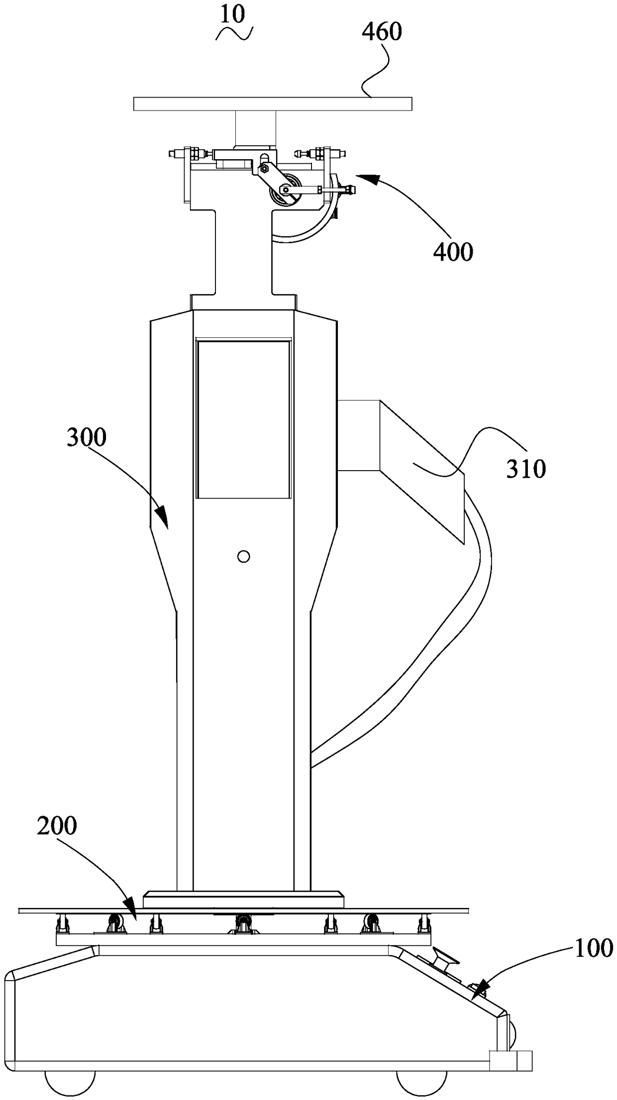
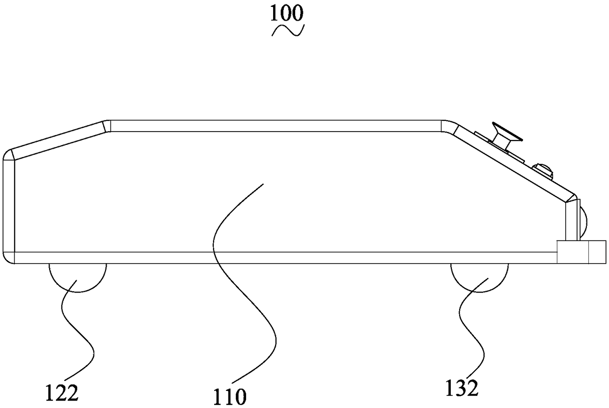
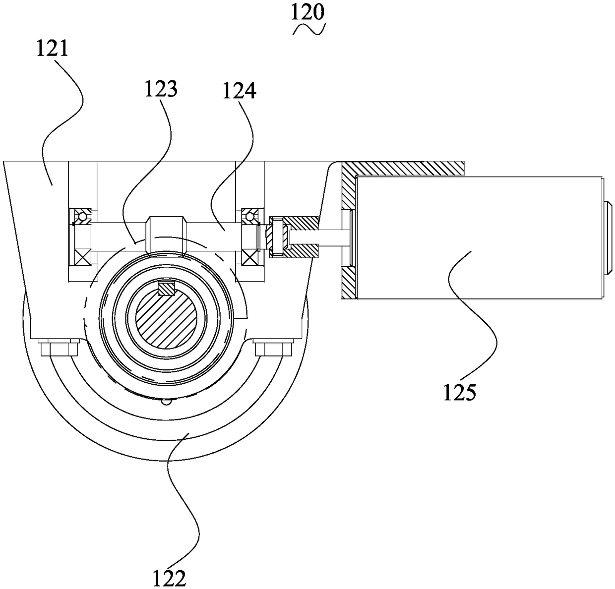
The invention discloses a solar charging pile which comprises a mobile device, a rotating device, a charging pile body and a solar power generation device. The moving device comprises a moving bearingplate, a main driving mechanism and a steering mechanism. The main driving mechanism comprises a main driving bracket, a main driving wheel, a worm gear, a worm and a main driving power part. The rotating device comprises a disk support assembly, a rotating disk and a rotating driving part. The charging pile body is arranged on a rotating disk, the charging pile body is provided with a storage battery and a charging gun electrically connected with the storage battery, and the solar power generation device is electrically connected with the storage battery. The solar charging pile, on the onehand, the whole movement of the solar charging pile can be realized, so that the solar charging pile can be moved from one position to another according to the actual situation, and on the other hand,the rotating function of the charging pile body can be realized, so that the panel for displaying information arranged on the charging pile body can be adjusted according to the actual situation.

Description

technical field [0001] The invention relates to the field of new energy technologies, in particular to a solar charging pile. Background technique [0002] Prior art 1 (CN107933355A), which discloses a solar charging pile, this kind of solar charging pile includes a charging part and a charging gun used to cooperate with the charging part, and the bottom surface of the charging part is provided with left and right opposite A left engaging groove and a right engaging groove, a passing groove is arranged between the left engaging groove and the right engaging groove, and the bottom surface of the charging part is between the left engaging groove and the right engaging groove A power outlet is provided, and a push block that can slide left and right is provided in the passage groove. In the present invention, the charging gun is locked firmly, and the charging gun is safe and stable to connect to the electricity. The whole device is convenient and quick to operate, which greatl...

Claims


Application Information

Patent Timeline
Patent Type & Authority Applications(China)
IPC IPC(8): B60L53/31B60L53/51H02J7/35H02S10/40H02S20/30
CPCH02S10/40H02S20/30H02J7/35Y02E10/50Y02T10/70Y02T90/12Y02T10/7072
Inventor 不公告发明人
Owner 太原市中一嘉强环保科技开发有限公司
Why Eureka
Try Eureka