
Clothes hook

A technology for hanging clothes hooks and fixing grooves, which is applied in the field of clothes hanging hooks, which can solve problems such as difficulty in thread matching rotation angle, clothes hooking, troublesome assembly, etc., and achieve good protection effect, avoid tilting, and good aesthetics

Pending Publication Date: 2019-06-18
李先楚
View PDF1 Cites 2 Cited by
  • Summary
  • Abstract
  • Description
  • Claims
  • Application Information

AI Technical Summary

Problems solved by technology

After the screw is screwed into the wall, a thread matching the screw will be formed in the screwed-in wall hole to form a fixed positioning effect on the screw. This is because the screw will be exposed directly after installation, which will cause the screw to rust. Reduce the service life of the product, and at the same time, when the clothes are taken out or put in, the clothes are easy to be hooked with the screws, which is easy to cause damage to the clothes
[0003] In order to solve the above problems, the Chinese patent application No. 201310704659.0 discloses a hook for a wardrobe with a screw hiding function, including a base and a hook assembly. The base is provided with two fixing holes, and the outside of the base is provided with There are external threads, and the hook assembly consists of a hook seat and a hook head. The hook seat is sleeved on the base and is threadedly connected with the external thread. The upper part of the hook head is welded and connected with the hook seat as a whole. This structure Although it is effective to prevent the screws from being exposed, the base and the hook need to be separated, and the base must be fixed on the wall with screws first, and then the hook must be fixed on the base, which is troublesome to assemble. At the same time, the hook is sleeved on the base through the hook seat It is difficult to control the rotation angle of the threaded connection, and it is difficult to control the orientation of the hook after assembly.

Method used


Image

  • Clothes hook
  • Clothes hook
  • Clothes hook

Examples


Embodiment Construction

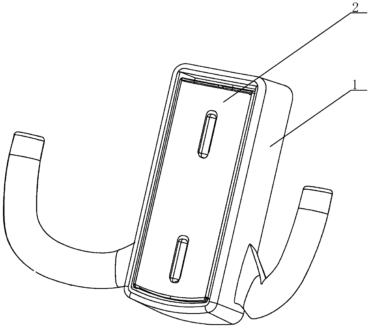
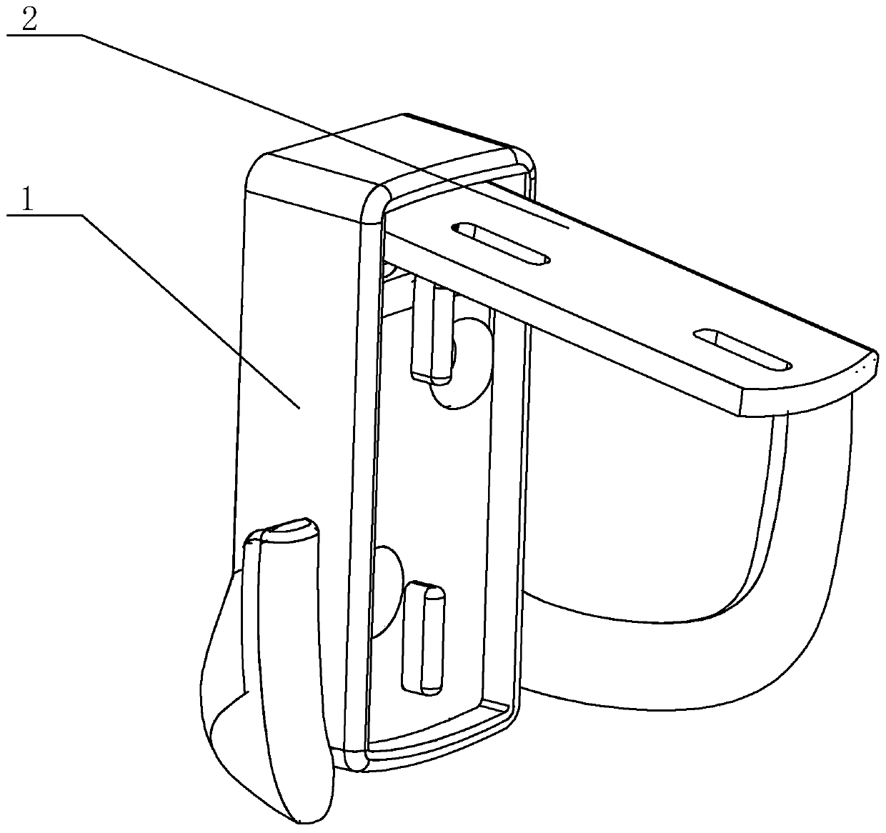
[0017] Refer to attached Figure 1 to Figure 5 An embodiment of a clothes hook of the present invention will be further described in detail.

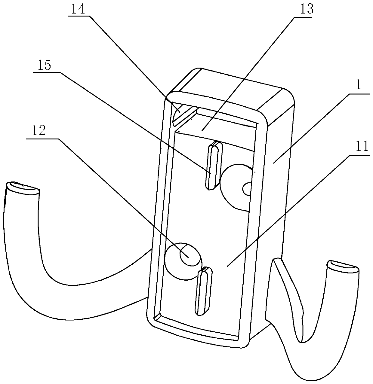
[0018] From figure 1 It can be seen that a clothes hook includes a hook main body 1 and a flap plate 2, from image 3 It can be seen that the hook main body 1 is provided with a fixing groove 11, which is formed by a downward depression of the end face of the hook main body 1, and the bottom wall of the fixing groove 11 is provided with a screw hole 12 for screw installation, and the screw hole 12 It can be a countersunk hole to prevent the screw from interfering with the clamshell 2, and the number of screw holes 12 is two, which are distributed along the diagonal line at intervals, so that the main body 1 of the hook can be more firmly fixed on the wall.

[0019] Described clamshell plate 2 is adapted with fixing groove 11, from Figure 5 It can be seen that the two sides of the upper end of the flip plate 2 are provided with rotat...


PUM


Abstract

The invention discloses a clothes hook. The clothes hook comprises a hook body and a flip cover plate and is characterized in that the hook body is provided with a fixing groove, the bottom wall of the fixing groove is provided with screw holes, the flip cover plate is matched with the fixing groove, and the upper end of the flip cover plate is rotatably arranged in the fixing groove. When clotheshook is mounted, a user only needs to press the upper end of the flip cover plate to allow the flip cover plate to rotate around the end so as to open the fixing groove and expose the screw holes, the hook body is fixed to the lateral wall of a wardrobe or a wall through screws penetrating the screw holes, and the flip cover plate rotates again to cover the fixing groove to complete the mountingof the clothes hook. Due to the fact that the flip cover plate covers the fixing groove, the screw holes and the screws cannot be seen, clothes placed in the wardrobe or hung on the clothes hook can be prevented from being damaged by the mounted screws, and good attractiveness is achieved due to the fact that the flip cover plate completely blocks the screws.

Description

technical field [0001] The invention relates to the field of clothes hangers, more specifically, it relates to a clothes hook. Background technique [0002] For the convenience of hanging clothes and other articles, people often set out clothes hooks on the wall. The hook bodies of existing clothes hooks are mostly directly fixed on the wall by screws. After the screw is screwed into the wall, a thread matching the screw will be formed in the screwed-in wall hole to form a fixed positioning effect on the screw. This is because the screw will be exposed directly after installation, which will cause the screw to rust. The service life of the product is reduced, and at the same time, when the clothes are taken out or put in, the clothes are likely to be hooked with the screws, thereby easily causing damage to the clothes. [0003] In order to solve the above problems, the Chinese patent application No. 201310704659.0 discloses a hook for a wardrobe with a screw hiding functio...

Claims


Application Information

Patent Timeline
IPC IPC(8): A47G25/06
Inventor 李先楚
Owner 李先楚
Learn More