Mop convenient in spin-drying

A mop and convenient technology, applied in the field of mops disclosed, can solve the problems of short mop lines, laborious removal of the mop head, low mopping efficiency, etc., and achieve the effects of convenient use, improved quality and efficiency, and simple and reasonable structure.

Inactive Publication Date: 2019-06-18
济宁市博韬玻璃制品有限公司
View PDF0 Cites 0 Cited by
  • Summary
  • Abstract
  • Description
  • Claims
  • Application Information

AI Technical Summary

Problems solved by technology

The mop line of this kind of rotary mop is relatively short, and the contact area is small when mopping the floor, so the efficiency of mopping the floor is not high. The connection between the mop rod and the mop head is connected by a turnbuckle, and it is laborious to disassemble the mop head.

Method used


Image

  • Mop convenient in spin-drying
  • Mop convenient in spin-drying

Examples


Embodiment Construction

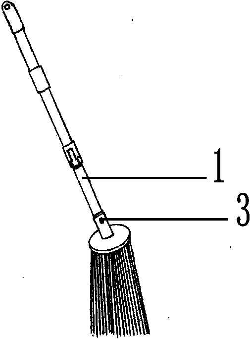
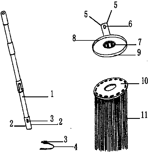
[0011] Below in conjunction with accompanying drawing, the present invention will be further described: as figure 1 and figure 2 Shown is a novel long-line mop that can be used for drying, consisting of a rotating mop rod 1, a mop seat, and a wire reel. There are two limit grooves 2, U-shaped shrapnel 4 inside the cavity of the connector head, and a spring button 3 at one end of the U-shaped shrapnel 4. 3. The inner wall passing through the cavity of the connector protrudes outside. The mop head is composed of a mop seat and a mop wire reel. The upper end of the mop seat is a hollow cylindrical sleeve, and the inner wall of the sleeve has two symmetrically protruding limit positions. Rib 5 penetrates through the wall of the cylindrical sleeve and is provided with a ring button to connect the through hole 6. The lower part of the mop seat is in the shape of a plastic disk, and its edge is a circle of grooves 9 formed in the center of the disk. The groove 9 There is a circle ...


PUM


Abstract

The invention discloses a mop convenient in spin-drying. The mop comprises a rotary mop rod and a mop head and is characterized in that a U-shaped elastic piece is arranged in the inner cavity of a connector between the mop rod and the mop head, a clamp spring button is arranged at one end of the elastic piece, the clamp spring button penetrates the inner wall of the cavity of the connector to extend out of the connector, and two limit grooves are symmetrically formed in the outer side of the cylindrical connector; the mop head comprises a mop seat and a mop thread plate, the upper end of mopseat is a hollow cylindrical sleeve, two protruding limit ribs are symmetrically arranged on the inner wall of the sleeve, and the wall of the cylindrical sleeve is provided with a clamp spring buttonbutt joint through hole penetrating the wall of the cylindrical sleeve. The long-thread mop has the advantages that the mop is simple in structure, the mop is coordinated with the rotary mop rod anda matched rotary mop bucket, spin-drying can be achieved, the mop rod and the mop head adopt a clamp spring type connecting manner, the mop head can be fast demounted and mounted, and cleaning efficiency and quality can be increased.

Description

technical field [0001] The invention discloses a mop, in particular to a mop which is convenient for drying. Background technique [0002] The traditional mop is to bind the mop line on a wooden pole to form a mop. The reason why this mop is still commonly used is that the mop line is relatively long and the efficiency of mopping the floor is high. But the biggest disadvantage of this kind of mop is that the moisture in the mop head must be wrung out by hand, which is very unsanitary and cannot be wrung out, which seriously affects the quality and efficiency of mopping the floor. When the mop line is worn out, the mop rod must be thrown away together, resulting in waste. [0003] At present, there is a rotary drying mop on the market. After the mop head of this mop is cleaned, the driving mechanism of the rotating mop rod is used. When the upper rod is pressed down, the lower rod will move relative to each other, and the mop head will drive the drying basket to rotate at a ...

Claims


Application Information

Patent Timeline
Patent Type & Authority Applications(China)
IPC IPC(8): A47L13/252A47L13/46A47L13/58
Inventor 陈静静
Owner 济宁市博韬玻璃制品有限公司
Why Eureka
Try Eureka