Linear straight-rail-type production system for textile bodies

A production system, straight-track technology, applied in textiles, papermaking, non-woven fabrics, etc., can solve the problems of low production line efficiency, restricting textile bodies, reducing material utilization, etc., to achieve good equipment connectivity and high production efficiency. Effect

Active Publication Date: 2019-06-18
武汉博瑞智信科技有限公司
View PDF6 Cites 3 Cited by
  • Summary
  • Abstract
  • Description
  • Claims
  • Application Information

AI Technical Summary

Problems solved by technology

[0004] The purpose of the present invention is to overcome the defects and problems of low production line efficiency, limit the shape of the textile body, and reduce the utilization rate of materials in the pri

Method used


Image

  • Linear straight-rail-type production system for textile bodies
  • Linear straight-rail-type production system for textile bodies
  • Linear straight-rail-type production system for textile bodies

Examples


Example Embodiment

[0059] Example 1:

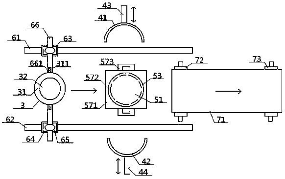
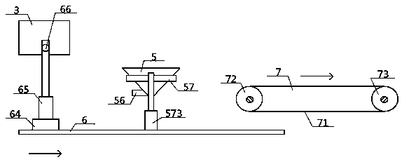
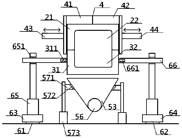
[0060] see figure 1 - Figure 15 , a linear straight track production system for textiles, comprising an outer sleeve 4, an air injection device 5, a linear guide rail 6, a conveying device 7, an upper mold 2 and a lower mold 3, and the upper mold 2 includes an upper mold body 21 And the upper mold cavity 22 provided inside, the lower mold 3 includes the lower mold body 31 and the lower mold cavity 32 provided inside, and the upper mold cavity 22 and the lower mold cavity 32 are butted up and down to form a molding cavity 1; The width of the inner wall of the sleeve 4 is greater than the width of the upper mold 2 and the lower mold 3, the height of the outer sleeve 4 is greater than the height of the upper mold 2, and the upper mold body 21 is provided with a plurality of upper ventilators communicating with the upper mold cavity 22. Road 25, the outer end of the upper air passage 25 communicates with the external environment of the upper mold 2, and the ...

Example Embodiment

[0061] Example 2:

[0062] Basic content is the same as embodiment 1, the difference is:

[0063] The air injection device 5 includes a lifting sleeve plate 57 and an air containment cover 53. The lifting cover plate 57 includes an outer plate body 571 and an inner sleeve opening 572 opened therein. The air containment cover 53 is a conical shape with a wide top and a narrow bottom. Body structure, the top of the air containment cover 53 is connected with the air outlet 51, the bottom end of the air containment cover 53 is connected with the intake pipe 56, the side wall of the air containment cover 53 is set in the inner sleeve port 572, and the outer plate body The side of 571 is connected with the output end of air cover lifting cylinder 573. The outside of the air outlet 51 is provided with an outer ring disc 52, and the top surface of the outer ring disc 52 is provided with a concentric inner air slide rail 54 and an outer air slide rail 55 around the position of the air...

Example Embodiment

[0064] Example 3:

[0065] Basic content is the same as embodiment 1, the difference is:

[0066] The outer sleeve 4 includes a left half sleeve 41 and a right half sleeve 42 arranged in pairs, the left side of the left half sleeve 41 is connected with the left driving device 43, and the right side of the left half sleeve 41 part and the left side of the right half-sleeve 42 to form an outer sleeve 4, and the right side of the right half-sleeve 42 is connected to the right driving device 44; the left driving device 43 and the right driving device 44 are all higher than the lower The mold 3 is provided, and the bottom ends of the left half sleeve 41 and the right half sleeve 42 are all lower than the top surface of the lower mold body 31 but higher than the bottom surface of the lower mold body 31.


PUM


Abstract

A linear straight-rail-type production system for textile bodies comprises an upper mold, a lower mold, an outer sleeve, an air injection device, linear guide rails and a conveying device. Each of theupper mold and the lower mold comprises an external mold body, a mold cavity and an air passage, and the mold cavities and the air passages are formed in the mold bodies and communicated with each other. The outer sleeve is higher than the upper mold. The linear guide rails include a first guide rail, and a second guide rail parallel to the first guide rail. The top ends of the first guide rail and the second guide rail are in sliding fit with the bottom surfaces of first and second sliding seats respectively. The top surfaces of the first sliding seat and the second sliding seat are connected with bottoms of mold lifting cylinders respectively. The output ends of the mold lifting cylinders are connected with the lateral portion of the lower mold through support shafts. An air outlet corresponding to an air inlet region is arranged at the top of the air injection device, and is clamped between the middle portions of the first guide rail and the second guide rail. The conveying deviceis arranged between the tail ends of the first guide rail and the second guide rail. The linear straight-rail-type production system has the advantages that streamline operation can be realized, and the production efficiency is high; the shapes of the textile bodies are not limited, and the utilization rate of materials can be increased.

Description

technical field [0001] The invention relates to a textile processing technology, which belongs to the field of textile machinery, in particular to a linear straight track production system of textiles. Background technique [0002] Textile body refers to a stable body formed by processing textile fibers. Its structure is mainly composed of textile fibers. Existing textile fibers include natural fibers and chemical fibers, and most of the existing processing techniques are to first make textile fibers The fibers are sequentially opened by raw materials, combed into a web, and then undergo various processing, such as warp and weft weaving, layer-by-layer stacking, vertical / horizontal web laying or their combination, and finally dried and cooled to obtain a molded body, that is, a textile body, not only The processing process is long, the process is numerous, the work efficiency is low, and the shape of the textile body is greatly limited. As a result, when making subsequent pr...

Claims


Application Information

Patent Timeline
IPC IPC(8): D04H1/76D04H1/558D04H3/07D04H3/14D04H5/10D04H5/06
Inventor 张智明王佳伟姬巧玲徐巧梅顺齐肖人彬
Owner 武汉博瑞智信科技有限公司
Why Eureka
Try Eureka