Collapse rockfill instability failure simulation device

A simulation device and rockfill technology, which are applied in the field of rockfill slump simulation experiments, and can solve problems such as the discount of the actual application value of the experimental results.

Active Publication Date: 2019-06-18
SOUTHWEST PETROLEUM UNIV
View PDF13 Cites 5 Cited by
  • Summary
  • Abstract
  • Description
  • Claims
  • Application Information

AI Technical Summary

Problems solved by technology

Most of the existing excitation devices are unable to meet the above requirements, so the simulation results are far from the objective reality, and the practical application value of the experimental results is greatly reduced

Method used


Image

  • Collapse rockfill instability failure simulation device
  • Collapse rockfill instability failure simulation device
  • Collapse rockfill instability failure simulation device

Examples


Embodiment 1

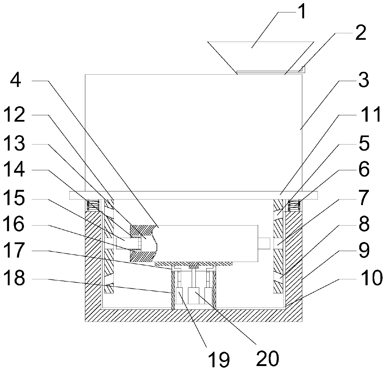
[0036] Such as Figure 1-7As shown, the present embodiment includes a simulation box 3, a base 9 positioned below the simulation box 3, a base plate 11 is provided at the bottom of the simulation box 3, and a plurality of springs 6 are respectively provided on the upper end surface of the base 9, and a plurality of The upper end of the spring 6 is connected to the lower end surface of the base plate 11, the base 9 has a cavity inside, and two hanging plates 12 are arranged on the lower surface of the base plate 11, each of the hanging plates 12 has an upper positioning The hole 5, the horizontal hole 7 and the lower positioning hole 8, and the upper positioning hole 5 and the lower positioning hole 8 are symmetrically distributed along the axis of the horizontal hole 7, and a support cylinder 18 is provided in the middle of the cavity of the base 9, and a support cylinder 18 is provided in the support cylinder 18. The top cylinder 20 and the two adjusting cylinders 19 are also...

Embodiment 2

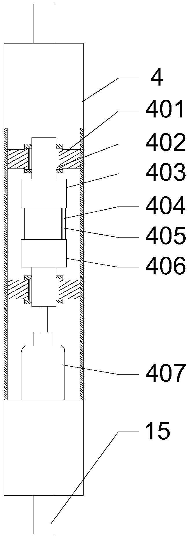
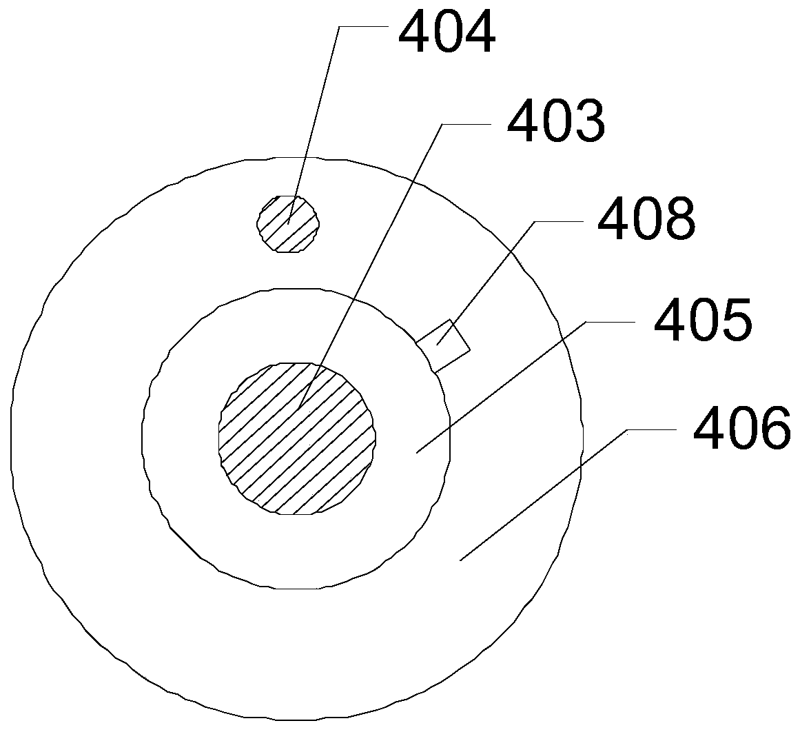
[0042] Such as figure 1 , 2 , 3, on the basis of Embodiment 1, this embodiment is provided with a cylindrical cavity inside the vibrating cylinder 4, and a motor 407 is provided along the axial direction of the cavity, and the output end of the motor 407 is A rotating shaft is provided, and two clamping plates 401 are arranged on the inner peripheral wall along the axial direction of the cavity, and a through hole is opened in the middle of each of the clamping plates 401, and bearings are respectively provided on both sides of the through hole, The outer peripheral wall of the rotating shaft is in contact with the inner peripheral walls of the four bearings respectively, and a static eccentric wheel 403 and a static eccentric wheel 406 are respectively fixed on the outer peripheral wall of the rotating shaft, and the static eccentric wheel 403 and the static eccentric wheel 406 are placed on Between the two clamping plates 401 , a moving eccentric 405 is rotated on the outer...

Embodiment 3

[0048] Such as Figure 7 As shown, this embodiment includes a cover plate 301 and four columns 304 respectively located on the lower surface of the cover plate 301, and also includes a terrain simulation plate 309, an active push-pull plate 314 and a door closer 315, and the adjacent two described The side walls of the columns 304 are provided with adjustment blocks 311, and each adjustment block 311 is provided with inferior arc grooves 312. The two side walls at one end of the terrain simulation board 309 are respectively hinged with the remaining two side walls of the columns 304. The two side walls of the other end of the terrain simulation board 309 are respectively provided with screw rods, and the screw rods move through the inferior arc groove 312 on the same side as the screw rods, and a matching locking head 313 is provided on the outer end of the screw rods, The cover plate 301 is provided with an open opening for the passing of the block stone 303, the housing of t...


PUM


Abstract

The invention discloses a collapse rockfill instability failure simulation device, which comprises a simulation box and a base. The lower surface of a bottom plate is provided with two hanging boards.Each hanging board is provided with an upper positioning hole, a horizontal hole and a lower positioning hole. The inner circumferential wall of a bearing plate is provided with two arc grooves in the circumferential direction. A clamp block is slidably arranged in each arc groove. The upper end of each clamp block protrudes out of the upper end surface of the arc groove. The two ends of a sliding groove are communicated with the lower ends of the two arc grooves respectively. The output end of an upper ejector cylinder is provided with an ejector rod. An elastic metal strip is hinged on theupper end of the ejector rod. The two end surfaces of an oscillation tube are respectively provided with a positioning groove in the middle. Each positioning groove is internally provided with a driving cylinder. The output end of the driving cylinder is connected with a pin column. The device is used for simulating stability of accumulation bodies under different geographic and geomorphic conditions and recording and analyzing corresponding experimental data, so that corresponding measures corresponding to the accumulation bodies under different geographic and geomorphic conditions are made to reduce loss due to collapse of the accumulation bodies.

Description

technical field [0001] The invention relates to a rockfill body slide simulation experiment, in particular to an indoor experimental device for simulating a secondary geological disaster source after an earthquake—the instability and destruction of a collapsed rockfill body. Effective implementation of rock mass instability protection measures. Background technique [0002] There is a common type of secondary geological disaster source in the southwestern region of my country where earthquakes occur frequently---collapsed rock-fill bodies, which are usually precipitous rock groups in mountainous areas that are triggered by strong earthquakes to collapse and slide, and large-scale rockfalls accumulate on the slope corners of the mountain made. Collapsed rockfills have the characteristics of significant material structure differentiation, random accumulation shape, loose accumulation metastable, sudden collapse and collapse, etc., which often bring great safety hazards to adja...

Claims


Application Information

Patent Timeline
Patent Type & Authority Applications(China)
IPC IPC(8): G01N29/04
Inventor 郭亮张军伟王保权李婧铷刘太鹏纪佑军张巧向莹曲宏略陈秋雨黄璐宋昊旻
Owner SOUTHWEST PETROLEUM UNIV
Why Eureka
Try Eureka