Laser radar calibration method and device, equipment and storage medium

A laser radar and calibration method technology, applied in the computer field, can solve the problems of low laser radar calibration efficiency and achieve the effect of improving calibration efficiency

Active Publication Date: 2019-06-18
WERIDE CORP
View PDF7 Cites 19 Cited by
  • Summary
  • Abstract
  • Description
  • Claims
  • Application Information

AI Technical Summary

Problems solved by technology

[0005] Based on this, it is necessary to provide a laser radar calibration method, device,

Method used


Image

  • Laser radar calibration method and device, equipment and storage medium
  • Laser radar calibration method and device, equipment and storage medium
  • Laser radar calibration method and device, equipment and storage medium

Examples


Embodiment Construction

[0047] The laser radar calibration method, device, equipment and storage medium provided in this application aim to solve the problem of low calibration efficiency. The technical solution of the present application and how the technical solution of the present application solves the above technical problems will be described in detail below through embodiments and in conjunction with the accompanying drawings. The following specific embodiments may be combined with each other, and the same or similar concepts or processes may not be repeated in some embodiments.

[0048] It should be noted that the laser radar calibration method provided in the embodiment of the present application can be applied not only in the scene of unmanned driving, but also in the scene of robot navigation, and the embodiment of the present application does not limit the specific application scene .

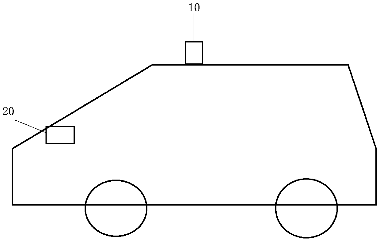
[0049] The lidar calibration method provided in this embodiment can be applied to such as figure 1 sh...


PUM


Abstract

The invention relates to a laser radar calibration method and device, equipment and a storage medium. A terminal, in a preset calibration scene, obtains a point cloud data frame pair of a to-be-calibrated laser radar; inertial navigation system data is obtained; and then through a calibration algorithm, a calibration result of the to-be-calibrated laser radar is determined according to the point cloud data frame pair and the inertial navigation system data. The calibration result of the to-be-calibrated laser radar can be automatically determined, so that the process of obtaining the calibration result of the laser radar by manual measurement is avoided, and the calibration efficiency of the laser radar is improved.

Description

technical field [0001] The present invention relates to the field of computer technology, in particular to a laser radar calibration method, device, equipment and storage medium. Background technique [0002] With the development of unmanned driving technology, on-board sensors are often used to obtain location information around the vehicle, and then plan, make decisions, or control autonomous vehicles based on the information detected by the sensors. [0003] Typically, in-vehicle sensors use multiple sensors to obtain location information around the vehicle. However, there are certain differences between the relative poses (including relative positions and orientations) of multiple sensors. It is necessary to calibrate the relative poses of multiple sensors so that the location information around the vehicle collected by multiple sensors is unified. To the same coordinate system, and then according to the position information in the same coordinate system, plan, make dec...

Claims


Application Information

Patent Timeline
IPC IPC(8): G01S7/497G01S17/93G01S17/42
CPCY02A90/10
Inventor 冯荻雷宇苍杜杭肯
Owner WERIDE CORP
Why Eureka
Try Eureka