Eureka AIR delivers breakthrough ideas for toughest innovation challenges, trusted by R&D personnel around the world.

LED device, fabrication method thereof and display panel

A technology of LED devices and display panels, which is applied in the direction of semiconductor devices, instruments, electrical components, etc., can solve the problem that the transmittance cannot meet the user's transmittance requirements, and achieve the effect of simple and transparent display

Active Publication Date: 2019-06-18
BOE TECH GRP CO LTD +1
View PDF9 Cites 5 Cited by
  • Summary
  • Abstract
  • Description
  • Claims
  • Application Information

AI Technical Summary

Problems solved by technology

Whether it is a transparent liquid crystal display panel or a transparent OLED display panel, its transmittance cannot meet the user's requirements for transmittance. Therefore, it is urgent to propose a new type of transparent display panel to improve the transmittance of the display panel.

Method used


Image

  • LED device, fabrication method thereof and display panel
  • LED device, fabrication method thereof and display panel
  • LED device, fabrication method thereof and display panel

Examples


no. 1 example

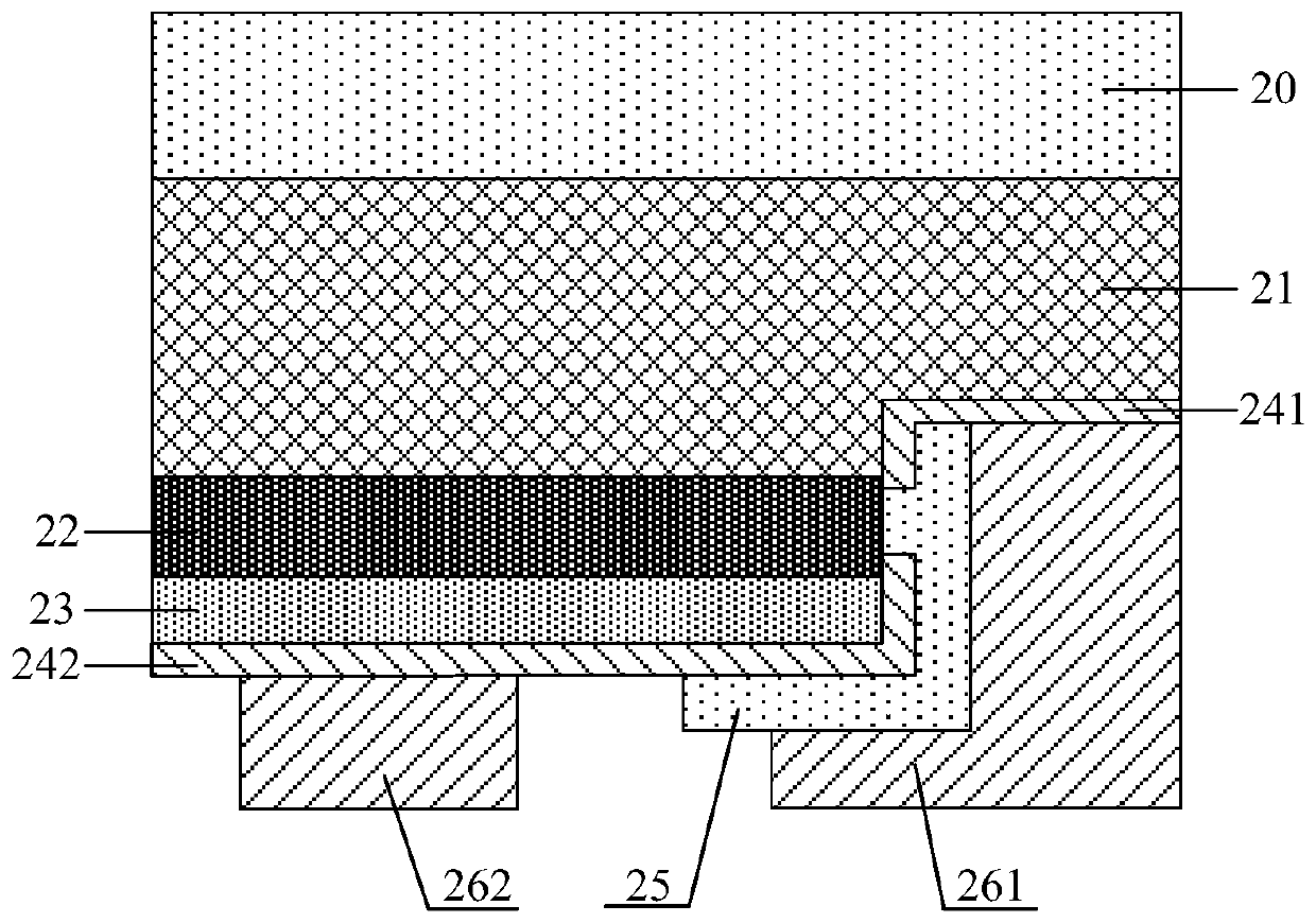
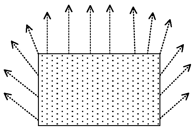
[0050] Figure 4 It is a schematic structural diagram of the LED device according to the first embodiment of the present invention. Figure 5 for Figure 4 Schematic diagram of the light output of the LED device shown. Such as Figure 4 As shown, the LED device includes a device structure layer disposed on a substrate 20 , and the device structure layer includes a first semiconductor layer 21 , a light-emitting functional layer 22 and a second semiconductor layer 23 disposed on the substrate 20 in sequence. The device structure layer also includes a first electrode 261 and a second electrode 262 . The first electrode 261 is electrically connected to the first semiconductor layer 21 , and the second electrode 262 is electrically connected to the second semiconductor layer 23 . The materials of the first electrode 261 and the second electrode 262 are both transparent materials. The LED device also includes a reflective layer 30 disposed on the peripheral side of the device ...

no. 2 example

[0068] Figure 7 It is a schematic structural diagram of the display panel according to the second embodiment of the present invention. Such as Figure 7 As shown, the display panel includes a transparent first substrate 50 and a plurality of LED devices 60 according to the first embodiment of the present invention disposed on the first substrate 50 .

[0069] In order to realize the transparency of the first substrate 50, the first substrate 50 may include a transparent substrate, such as a glass substrate or the like. The first substrate 50 may further include a first control wiring and a second control wiring disposed on a side of the transparent substrate facing the LED device 60 . The first control wiring is used to electrically connect with the first electrode of the LED device and provide a corresponding working voltage to the first electrode, and the second control wiring is used to electrically connect to the second electrode of the LED device and provide a correspo...


PUM


Abstract

The invention discloses an LED device, a fabrication method thereof and a display panel. The LED device comprises a device structure layer, wherein the device structure layer comprises a first semiconductor layer, a light-emitting functional layer and a second semiconductor layer which are sequentially arranged, the LED device also comprises a light-emitting layer, and the light-emitting layer isarranged on a peripheral side surface of the device structure layer. The display panel comprises a transparent first substrate and a plurality of LED devices, wherein the plurality of LED devices arearranged on the first substrate, and light can be emitted simultaneously from a top surface and a bottom surface of each LED device; with the arrangement of the light-emitting layer, the light giving-out brightness of the top surface and the bottom surface of the LED device is further improved, thus, the display panel proposed by the embodiment is a transparent display panel and has relatively high transmittance, and the requirement of a user on the transmittance of the display panel can be met.

Description

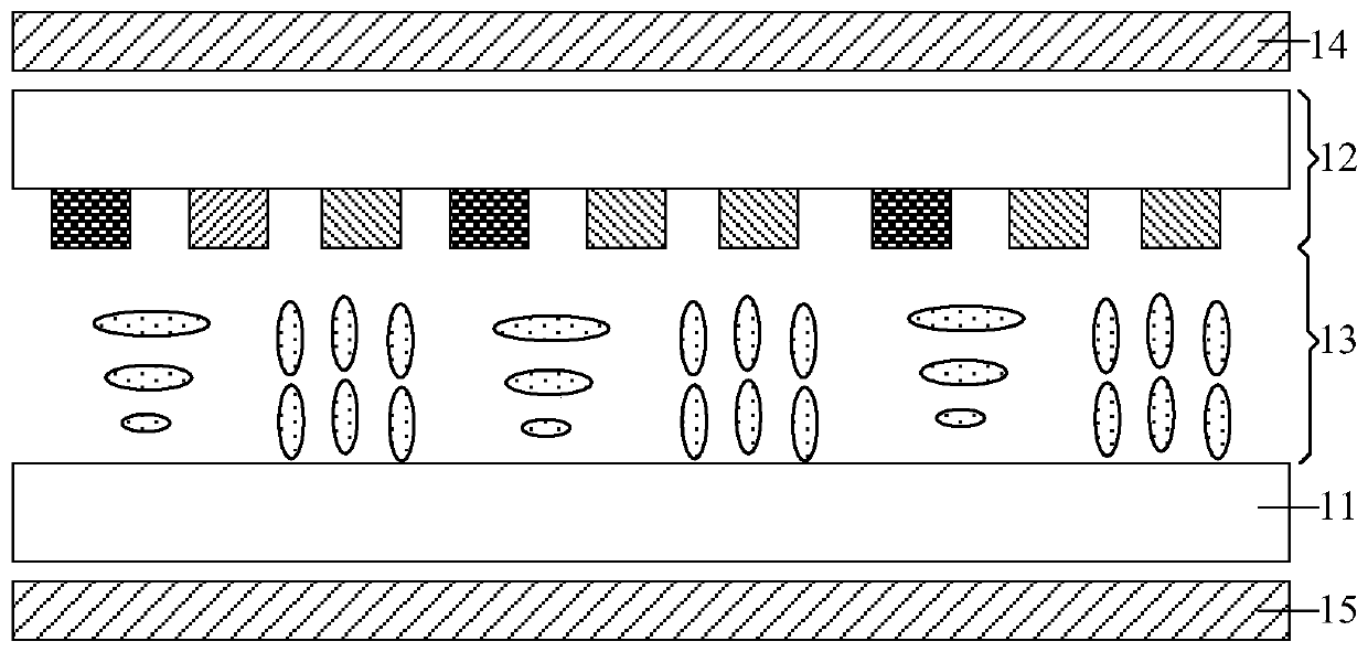
technical field [0001] The invention relates to the field of display technology, in particular to an LED device, a manufacturing method thereof, and a display panel. Background technique [0002] With the development of technology, there have been transparent display panels installed on glass windows. This panel can not only be used for display, but also people can see the items behind the window through the display panel. In order to improve the cleanliness of items behind the viewing window, users have higher and higher requirements for the transmittance of transparent display panels. [0003] Existing transparent display panels mainly include transparent liquid crystal display panels and transparent OLED display panels. figure 1 It is a structural schematic diagram of a transparent liquid crystal display panel, figure 1 The shown transparent display panel includes an array substrate 11 and a color filter substrate 12 arranged in opposite positions, and also includes a l...

Claims


Application Information

Patent Timeline
IPC IPC(8): H01L33/46H01L33/42H01L33/48H01L33/62H01L33/00G09F9/33
Inventor 李冬磊刘辉陈英余鸿昊刘珊珊王伯长贾丽丽
Owner BOE TECH GRP CO LTD
Why Eureka
Eureka Blog
Learn More