Wireless network data transmission method, sending end and receiving end

A technology of wireless network data and transmission method, applied to the transmitting end and the receiving end, in the field of wireless network data transmission method, can solve the problems of multiple resources, consumption, low data transmission efficiency, etc., to reduce the probability of loss, reduce the number of transmissions, The effect of reduced time

Active Publication Date: 2019-06-18
CHINANETCENT TECH
View PDF4 Cites 1 Cited by
  • Summary
  • Abstract
  • Description
  • Claims
  • Application Information

AI Technical Summary

Problems solved by technology

[0005] Since the current response message fed back by the receiver is usually in one-to-one correspondence with the data message sent by the sender, the sender will frequently update the window value, causing the sender to consume more time in updating the window value. Resources
In addition, when the wireless network fluctuates, due to the large number of response packets, the number of response packets that may be lost will also be large
In this way, the sender may not be able to receive part of the response message, and thus cannot update the window value in time
The window value will limit the number of data packets sent, which will cause the sender to be unable to effectively use the wireless network bandwidth, resulting in low data transmission efficiency

Method used


Image

  • Wireless network data transmission method, sending end and receiving end
  • Wireless network data transmission method, sending end and receiving end
  • Wireless network data transmission method, sending end and receiving end

Examples


Embodiment 1

[0021] The present application provides a wireless network data transmission method, the method can be applied to a sending end, and the sending end can be a terminal device supporting a wireless network. For example, the sending end may be a router. Certainly, the sending end may also be an electronic device used by the user. For example, the sending end may be a desktop computer, a notebook computer, a tablet computer, a smart phone, a smart wearable device, etc. that support a wireless network. see figure 1 and figure 2 , the method may include the following steps.

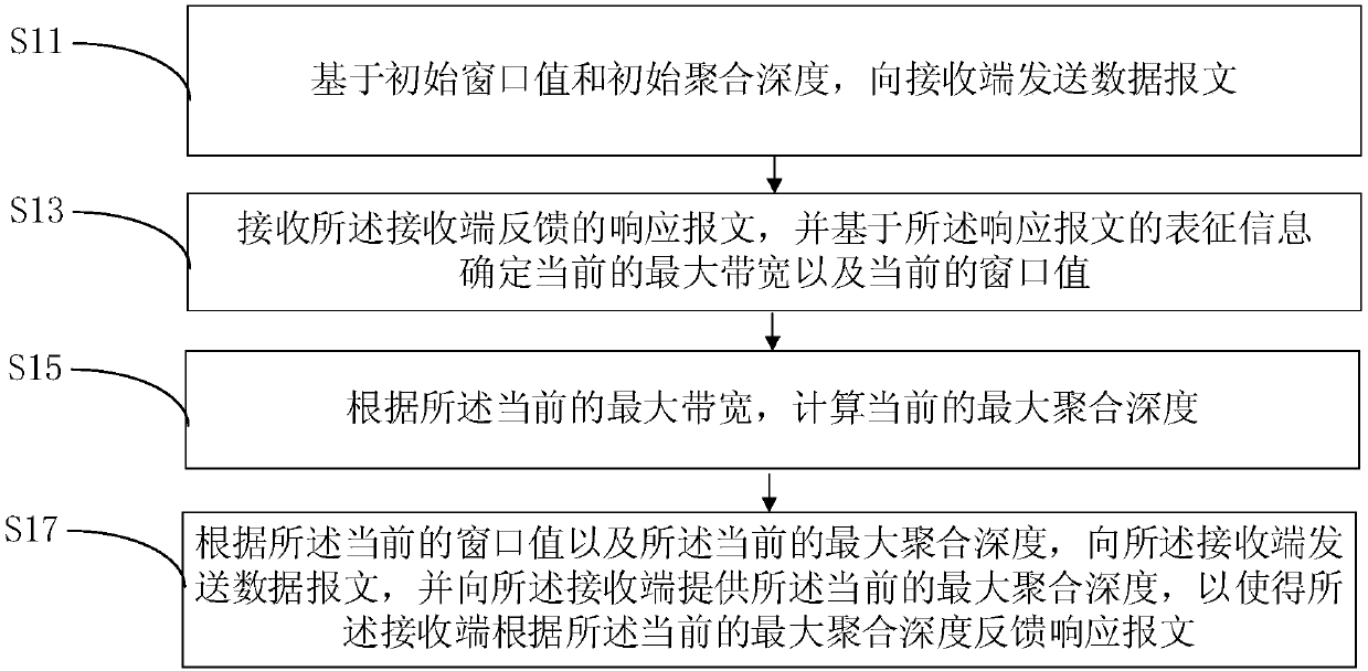
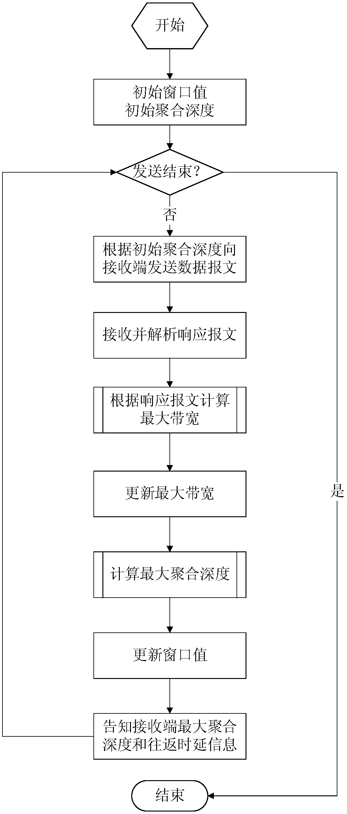
[0022] S11: Based on the initial window value and the initial aggregation depth, send a data packet to the receiving end.

[0023] In this implementation manner, when the sender starts to send the data packet to the receiver, the data packet may be sent based on the initial window value and the initial aggregation depth. The initial window value and the initial aggregation depth may be preset according to...

Embodiment 2

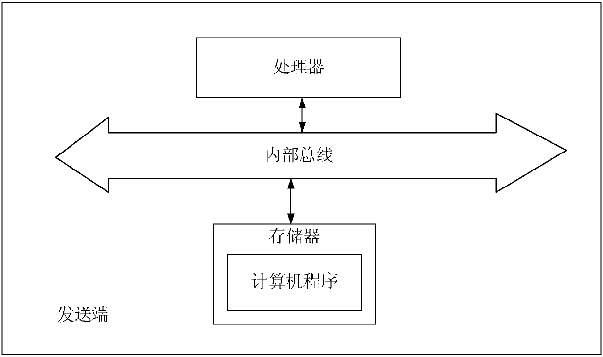
[0046] Please also refer to figure 1 and image 3 , the present application also provides a sending end, the sending end includes a processor and a memory, a computer program is stored in the memory, and when the computer program is executed by the processor, the following steps are implemented:

[0047] S11: Based on the initial window value and the initial aggregation depth, send a data message to the receiving end;

[0048] S13: Receive a response message fed back by the receiving end, and determine a current maximum bandwidth and a current window value based on the characterization information of the response message;

[0049] S15: Calculate the current maximum aggregation depth according to the current maximum bandwidth;

[0050] S17: Send a data packet to the receiving end according to the current window value and the current maximum aggregation depth, and provide the receiving end with the current maximum aggregation depth, so that the receiving end The current maxim...

Embodiment 3

[0052] The present application also provides a wireless network data transmission method, the method can be applied to a receiving end, and the receiving end can be a terminal device used by a user. For example, the receiving end may be a desktop computer, a notebook computer, a tablet computer, a smart phone, a smart wearable device, etc. that support a wireless network. see Figure 4 and Figure 5 , the method includes the following steps.

[0053] S21: Receive the data message from the sender and the maximum aggregation depth.

[0054] In this implementation manner, the sending end may send data packets to the receiving end according to a specified time period. For example, the specified time period may be 1 ms, so that the sending end may send a data packet to the receiving end every 1 ms. Wherein, in each time period, the number of data packets sent by the sender may be the same as the maximum aggregation depth. For example, if the maximum aggregation depth is 6, the...


PUM


Abstract

The invention discloses a wireless network data transmission method, a sending end and a receiving end, and the method comprises the steps: sending a data message to the receiving end based on an initial window value and an initial aggregation depth; receiving a response message fed back by the receiving end, and determining the current maximum bandwidth and the current window value based on the representation information of the response message;calculating the current maximum aggregation depth according to the current maximum bandwidth; and according to the current window value and the current maximum aggregation depth, sending a data message to the receiving end, and providing the current maximum aggregation depth for the receiving end, so that the receiving end feeds back a response message according to the current maximum aggregation depth. According to the technical scheme provided by the invention, the data transmission efficiency can be improved.

Description

technical field [0001] The invention relates to the technical field of the Internet, in particular to a wireless network data transmission method, a sending end and a receiving end. Background technique [0002] With the continuous development of Internet technology, wireless networks have become one of the main carriers of current network traffic. In the wireless network, the Wi-Fi network is currently the main access mode of the wireless terminal. [0003] When transmitting data on a Wi-Fi network, the sender usually determines the number of packets that can be sent according to the current window value. The window value is usually determined by the response message fed back by the receiver. Therefore, in the current Wi-Fi network, the response packet usually determines the number of packets that the sender can send. [0004] At present, whenever the sender sends a data message to the receiver, the receiver will feed back a corresponding response message for the receive...

Claims


Application Information

Patent Timeline
Patent Type & Authority Applications(China)
IPC IPC(8): H04L12/807H04L12/891H04W28/10H04L47/27H04L47/41
CPCH04L1/00H04W28/06H04W28/10H04W28/0236H04L47/27H04L47/266H04L47/28H04L41/0896H04W28/20H04W72/0446
Inventor 陈晓彬陈文生陈伟龙
Owner CHINANETCENT TECH
Why Eureka
Try Eureka