Flue gas desulfurizing tower based on Karman vortex street

A desulfurization tower and flue gas technology, applied in the field of desulfurization, can solve the problems of nozzle clogging, difficulty in cleaning, and increased use costs, and achieve the effect of reducing use costs and improving scaling problems

Inactive Publication Date: 2019-06-21
JISHOU UNIVERSITY
View PDF3 Cites 2 Cited by
  • Summary
  • Abstract
  • Description
  • Claims
  • Application Information

AI Technical Summary

Problems solved by technology

Due to the high temperature of the spray pipe, when the water evaporates, it is easy to scale on the inner wall of the spray pipe, especially it is easy to cause the nozzle to be blocked.
It is also difficult to remove the scale accumulated in these spray pipes and nozzles. Whether it is cleaning or replacing the spray pipes, it will inevitably increase the cost of use.

Method used


Image

  • Flue gas desulfurizing tower based on Karman vortex street
  • Flue gas desulfurizing tower based on Karman vortex street
  • Flue gas desulfurizing tower based on Karman vortex street

Examples


Embodiment 1

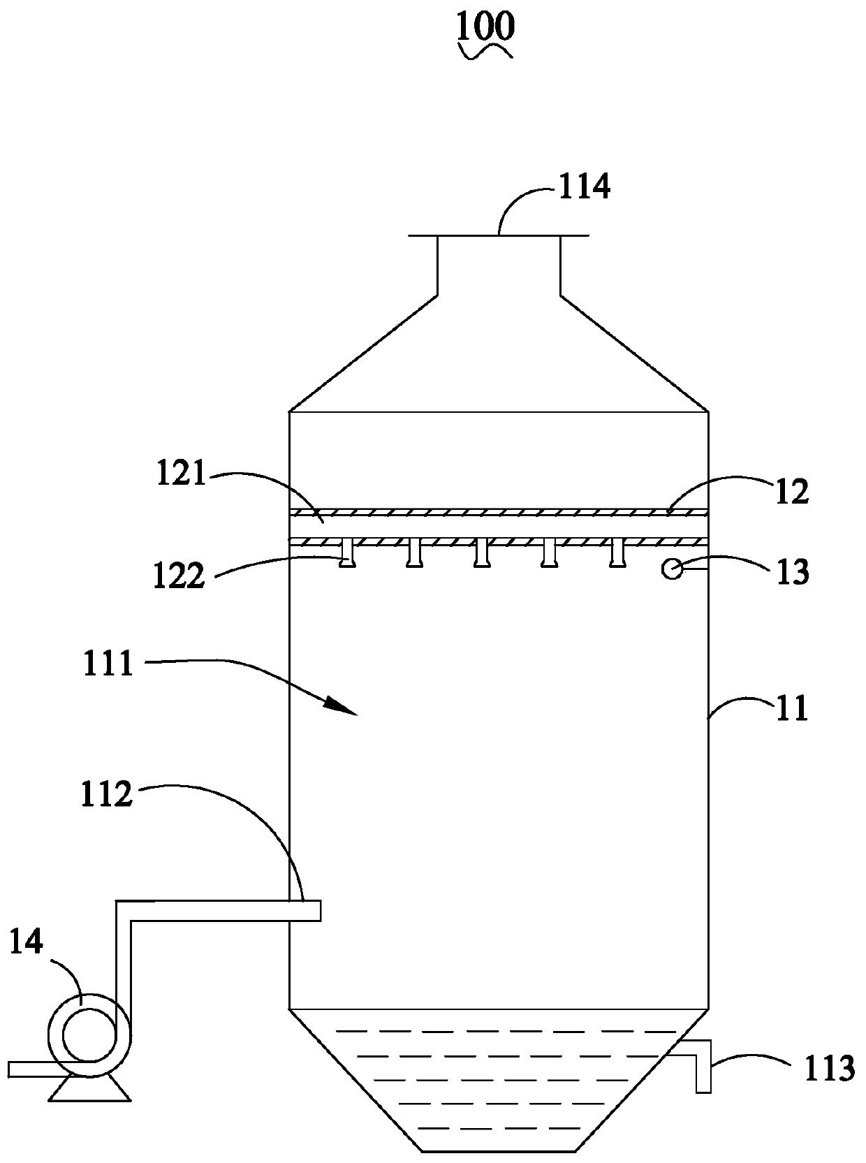
[0029] see figure 1 As shown, the present invention provides a Karman vortex street-based flue gas desulfurization tower 100, including a housing 11 with an internal cavity 111 and a cylindrical Karman vortex street generator 12 disposed in the internal cavity 111, so The bottom of the casing 11 is provided with a flue gas inlet 112 and a water outlet 113, and the top is provided with a gas outlet 114, containing SO 2 The flue gas flows into the housing 11 through the flue gas inlet 112, and the Karman vortex street phenomenon is generated after the flue gas flows through the Karman vortex street generator 12, and the vortex generates on the Karman vortex street generator 12. The periodic alternating lateral force drives the Karman vortex generator 12 to vibrate to achieve the purpose of automatic descaling.

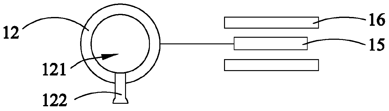
[0030] The Karman vortex generator 12 includes a spray pipe 121 arranged inside it along its length direction and a plurality of nozzles 122 arranged in an array along ...

Embodiment 2

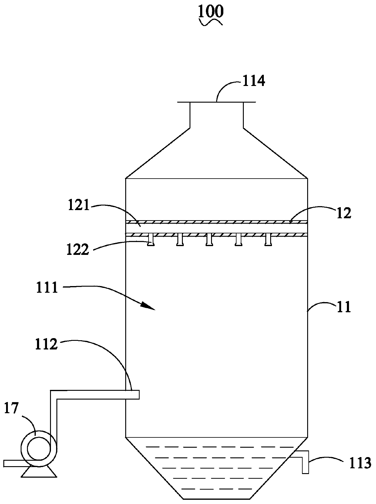
[0034] see figure 2 As shown, the present invention provides a Karman vortex street-based flue gas desulfurization tower 100, including a housing 11 with an internal cavity 111 and a cylindrical Karman vortex street generator 12 disposed in the internal cavity 111, so The bottom of the casing 11 is provided with a flue gas inlet 112 and a water outlet 113, and the top is provided with a gas outlet 114, containing SO 2 The flue gas flows into the housing 11 through the flue gas inlet 112, and the Karman vortex street phenomenon is generated after the flue gas flows through the Karman vortex street generator 12, and the vortex generates on the Karman vortex street generator 12. The periodic alternating lateral force drives the Karman vortex generator 12 to vibrate to achieve the purpose of automatic descaling.

[0035] The Karman vortex generator 12 includes a spray pipe 121 arranged inside it along its length direction and a plurality of nozzles 122 arranged in an array along...


PUM


Abstract

The invention provides a flue gas desulfurizing tower based on Karman vortex street. The flue gas desulfurizing tower comprises a casing with an internal cavity and a cylindrical Karman vortex streetgenerator arranged in the internal cavity, wherein the cylindrical Karman vortex street generator comprises a spraying liquid pipeline arranged in the cylindrical Karman vortex street generator alongthe length direction of the cylindrical Karman vortex street generator and a plurality of spouts which are arranged in an array form along the length direction of the cylindrical Karman vortex streetgenerator and are communicated with the spraying liquid pipeline; a flue gas inlet is formed in the bottom of the casing; flue gas containing SO2 flows into the casing through the flue gas inlet. Theflue gas desulfurizing tower provided by the invention has the beneficial effects that the Karman vortex street phenomenon is applied in the desulfurizing tower; scales in the spraying liquid pipelineare automatically cleared by vibration generated by the Karman vortex street phenomenon to the Karman vortex street phenomenon generator, so that the problem of scaling in the spraying liquid pipeline is obviously improved and the use cost of the flue gas desulfurizing tower is reduced.

Description

[0001] 【Technical field】 [0002] The invention relates to the technical field of desulfurization, in particular to a Karman vortex street-based flue gas desulfurization tower. [0003] 【Background technique】 [0004] When the fluid bypasses a bluff object, the paired, alternately arranged, antisymmetric vortices with opposite rotation directions generated on the left and right sides of the object's wake are called Karman vortex streets. Karman vortex street is a phenomenon studied in viscous incompressible fluid dynamics. Karman vortex street will be generated when fluid flows around tall chimneys, high-rise buildings, wires, oil pipelines and tube bundles of heat exchangers. When a vortex street appears, the fluid will produce a periodic alternating lateral force on the object. If the frequency of the force is close to the natural frequency of the object, it will cause resonance and even damage the object. This vortex street has made the periscope of the submarine lose its...

Claims


Application Information

Patent Timeline
Patent Type & Authority Applications(China)
IPC IPC(8): B01D53/78B01D53/50B08B9/027
Inventor 史凯刘春琼
Owner JISHOU UNIVERSITY
Why Eureka
Try Eureka