
Machining tool and method of centrifugal compressor

A technology for centrifugal compressors and processing methods, which is applied in the direction of drilling molds for workpieces, etc., and can solve the problems of difficult guarantee of machining accuracy and low yield of centrifugal compressors, etc.

Active Publication Date: 2019-06-21
BEIHANG UNIV
View PDF7 Cites 1 Cited by
  • Summary
  • Abstract
  • Description
  • Claims
  • Application Information

AI Technical Summary

Problems solved by technology

[0005] The purpose of the present invention is to provide a processing tooling and processing method for a centrifugal compressor to solve the problems that the processing accuracy of the centrifugal compressor is not easy to guarantee and the yield is low

Method used


Image

  • Machining tool and method of centrifugal compressor
  • Machining tool and method of centrifugal compressor
  • Machining tool and method of centrifugal compressor

Examples


Embodiment Construction

[0035] The core of the present invention is to provide a processing tool and processing method for a centrifugal compressor, which solves the problems that the processing accuracy of the centrifugal compressor is not easy to guarantee and the yield is low.

[0036] In order to enable those skilled in the art to better understand the technical solutions provided by the present invention, the present invention will be further described in detail below in conjunction with the accompanying drawings and specific embodiments.

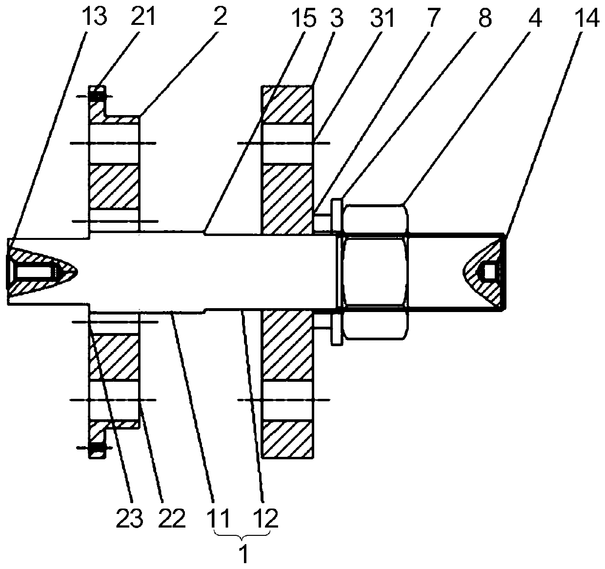
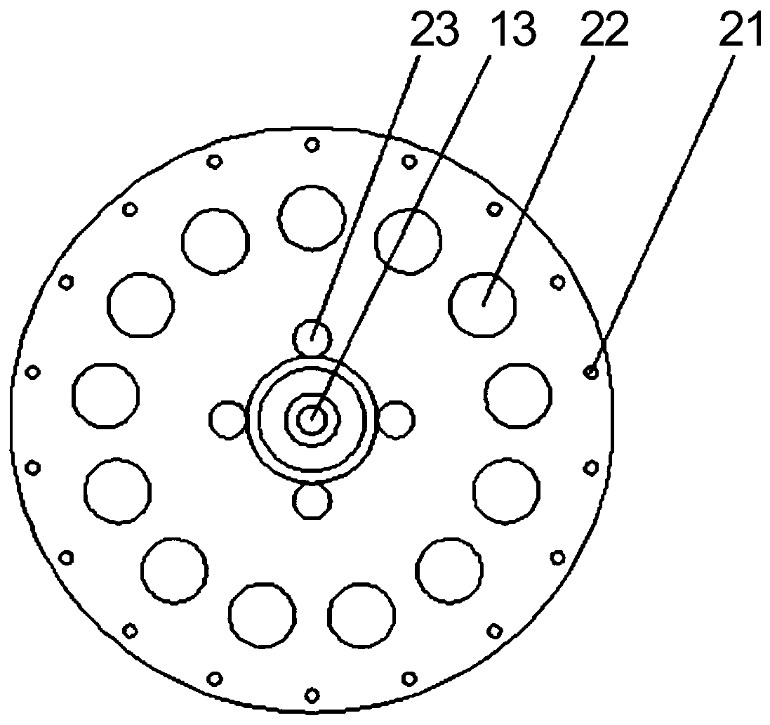
[0037] Such as Figure 1-Figure 6 As shown, a processing tool for a centrifugal compressor provided by an embodiment of the present invention includes a mandrel 1, a first pressure plate 2, a second pressure plate 3 and a compression nut 4; wherein, the first pressure plate 2 is coaxial and The relative position is fixed on the mandrel 1, and it is arranged near the end of the mandrel 1. The first pressure plate 2 is provided with the first positioning hole 2...


PUM


Abstract

The invention discloses a machining tool and method for a centrifugal compressor. The machining tool comprises a mandrel, a first pressure plate, a second pressure plate and a compression nut. The first pressure plate is coaxially arranged on the mandrel with a relative position fixed, and is disposed near the end part of the mandrel. The first pressure plate is provided with first positioning holes and first through holes for riveting which are used for fixing a casing. A second through hole is formed in the axial center position of the second pressure plate, and the second through hole slidably sleeves the mandrel. The second pressure plate is provided with second through holes for riveting corresponding to the positions of pre-machined riveting holes of a diffuser in a one-to-one mode,and at the same time, the positions of the second through holes for riveting are in one-to-one correspondence with the positions of the first through holes the riveting. The compression nut is in screw thread fit with the mandrel, and the compression nut is used for pressing the second pressure plate to the first pressure plate. The machining tool solves the problem that installation cannot be performed due to misalignment of the riveting holes, and then improves the yield of the riveting installation.

Description

technical field [0001] The invention relates to the technical field of centrifugal compressors, in particular to a processing tool and a processing method for centrifugal compressors. Background technique [0002] Centrifugal compressor is an important part of turbocharger, which is widely used because of its high single-stage boost ratio and simple structure. Compressor case and diffuser are important parts of centrifugal compressor, so their performance directly affects the performance of centrifugal compressor. The inside of the compressor casing is fitted with a rotating impeller, which puts forward higher requirements on the coaxiality of the compressor casing and the diffuser. [0003] At present, the manufacturing process of the centrifugal compressor mainly adopts the method of separate processing and reassembly. This processing method is difficult to ensure the coaxiality of the compressor casing and the diffuser, and it is very easy to appear that the impeller is ...

Claims


Application Information

Patent Timeline
Patent Type & Authority Applications(China)
IPC IPC(8): B21J15/14B21J15/38B23B47/28
Inventor 邹正平漆鑫付超李欢张玉国
Owner BEIHANG UNIV
Learn More