pneumatic tire

A technology of pneumatic tires and sipes, which is applied to road vehicle tires, off-road vehicle tires, tire parts, etc., can solve the problem of rigidity reduction and achieve the effect of ensuring grounding

Active Publication Date: 2020-12-18
TOYO TIRE & RUBBER CO LTD
View PDF7 Cites 0 Cited by
  • Summary
  • Abstract
  • Description
  • Claims
  • Application Information

AI Technical Summary

Problems solved by technology

[0006] However, there is also a problem that the rigidity of the land portion of the tread decreases due to the provision of the sipe.

Method used


Image

  • pneumatic tire
  • pneumatic tire
  • pneumatic tire

Examples


Embodiment Construction

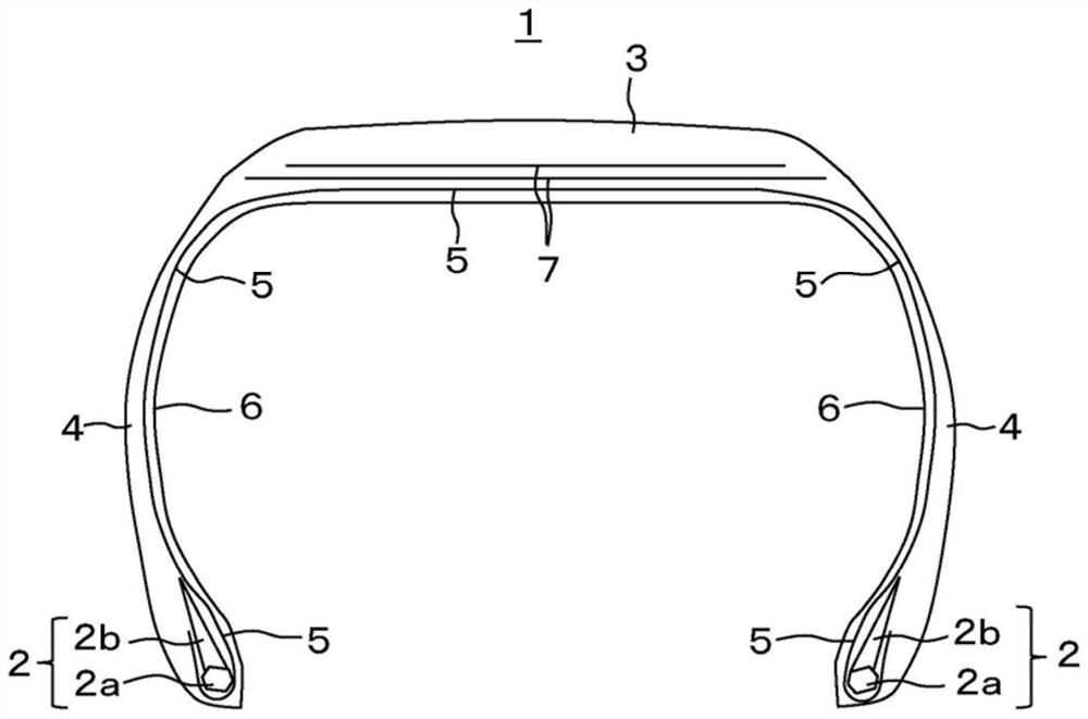
[0015] like figure 1 As shown by way of example, bead portions 2 are provided on both sides in the tire width direction of the pneumatic tire 1 . The bead portion 2 includes: a bead core 2a formed of a steel wire wound in a circular shape; and a rubber bead apex 2b provided radially outside the bead core 2a. A carcass ply 5 is bridged over the bead portions 2 on both sides in the tire width direction. The carcass ply 5 is a sheet-like member in which a plurality of cords arranged in a direction perpendicular to the tire circumferential direction are covered with rubber. The carcass ply 5 forms the skeleton shape of the pneumatic tire 1 between the bead portions 2 on both sides in the tire width direction, and is folded around the bead portion 2 from inside to outside in the tire width direction to wrap the bead portion 2 . A sheet-shaped inner liner 6 made of rubber with low air permeability is pasted inside the carcass ply 5 .

[0016] One or more layers of the belt 7 are ...


PUM


Abstract

The present invention relates to a pneumatic tire. To provide a pneumatic tire that can ensure ground contact while reducing the rigidity of a land portion as much as possible. The pneumatic tire has: a pattern block (41) formed by main grooves (15) and lateral grooves (20, 25); 45), the pneumatic tire is characterized in that the block longitudinal sipe (45) is a zigzag shape formed by: a plurality of longitudinal sipe parts (42) extending along the tire circumferential direction; and along the tire width The transverse sipe portion (43) extending in the direction and connecting the ends of the two longitudinal sipe portions (42) to each other is closer to the longitudinal sipe portion (42) on the push-out side of the block (41). ) the smaller the width.

Description

[0001] This application is based on Japanese patent application 2017-238858 (application date: December 13, 2017) and claims the priority of Japanese patent application 2017-238858. This application contains the entire content of Japanese patent application 2017-238858. technical field [0002] The present invention relates to a pneumatic tire. Background technique [0003] As described in Patent Document 1 and Patent Document 2, it is known that a land portion of a tread of a pneumatic tire is provided with a sipe extending in the tire circumferential direction. It is considered that the ground contact performance of the land portion of such a tread is improved by the effect of the sipes. [0004] Patent Document 1: Japanese Patent Laid-Open No. 2011-116319 [0005] Patent Document 2: Japanese Patent Laid-Open No. 2000-318413 Contents of the invention [0006] However, there is also a problem that the rigidity of the land portion of the tread decreases due to the provi...

Claims


Application Information

Patent Timeline
Patent Type & Authority Patents(China)
IPC IPC(8): B60C11/12B60C11/03
CPCB60C11/0302B60C11/0309B60C11/032B60C11/1204B60C11/1236B60C11/1281B60C11/1307B60C2011/0346B60C2011/0358B60C2011/0381B60C2011/0383B60C2011/0388B60C2011/1213B60C2011/1245B60C2011/1254B60C2011/133B60C2200/04B60C2200/14B60C11/1263B60C2011/0334B60C2011/1227
Inventor 安永智一
Owner TOYO TIRE & RUBBER CO LTD
Why Eureka
Try Eureka