
Multi-input multi-output power system and control method for rotary wing aircraft

A technology of rotating wings and power systems, applied to the transmission device driving multiple propellers, the type of power device, the type of power plant, etc., can solve the problems of heavy structural mass, single design state, complex design state, etc., to achieve The effects of improving flight efficiency, improving working conditions, and increasing working life

Active Publication Date: 2022-04-01
南京灵龙旋翼无人机系统研究院有限公司
View PDF8 Cites 0 Cited by
  • Summary
  • Abstract
  • Description
  • Claims
  • Application Information

AI Technical Summary

Problems solved by technology

[0008] 1. The structural quality is very heavy. For example, the existing friction clutch structure that realizes the connection and disconnection of different power sources is very heavy, and it is difficult to meet the take-off weight requirements of rotary wing aircraft
[0009] 2. In fact, the electric drive part of a gasoline-electric hybrid vehicle only plays an auxiliary role in saving fuel, and the design state is single; while a rotary-wing aircraft has multiple flight stages, in different flight stages, its corresponding input power The requirements are different, so it is necessary to comprehensively design multiple input sources according to the requirements of different flight stages, and the design state is complicated
[0010] 3. The output of the power system of the gasoline-electric hybrid vehicle is a single output, and the output form is simple, which is not suitable for the multi-output requirements of the rotary wing aircraft; in the rotary wing aircraft, due to the existence of multiple flight stages, the power system Power output devices such as main rotor, front pull / back push propeller, and tail rotor are required, and a multi-output design that is different from the single output of existing gasoline-electric hybrid vehicles must be designed

Method used


Image

  • Multi-input multi-output power system and control method for rotary wing aircraft
  • Multi-input multi-output power system and control method for rotary wing aircraft

Examples


Embodiment Construction

[0040] Embodiments of the present invention are described in detail below, examples of which are shown in the drawings, wherein the same or similar reference numerals designate the same or similar elements or elements having the same or similar functions throughout. The embodiments described below by referring to the figures are exemplary and are intended to explain the present invention and should not be construed as limiting the present invention.

[0041] In describing the present invention, it should be understood that the terms "center", "longitudinal", "transverse", "length", "width", "thickness", "upper", "lower", "front", " Orientation indicated by rear, left, right, vertical, horizontal, top, bottom, inside, outside, clockwise, counterclockwise, etc. The positional relationship is based on the orientation or positional relationship shown in the drawings, which is only for the convenience of describing the present invention and simplifying the description, rather than ...


PUM


Abstract

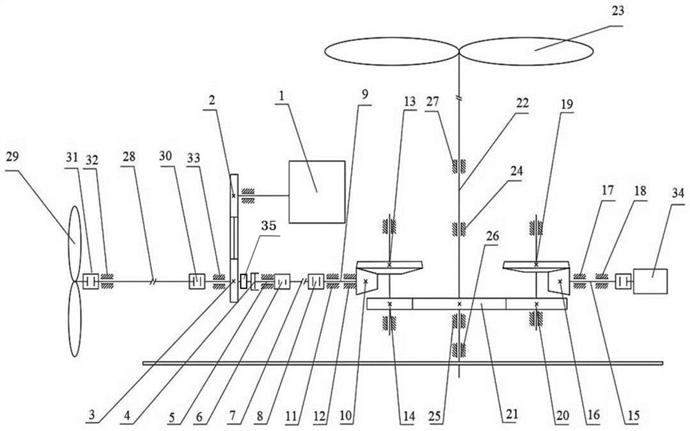
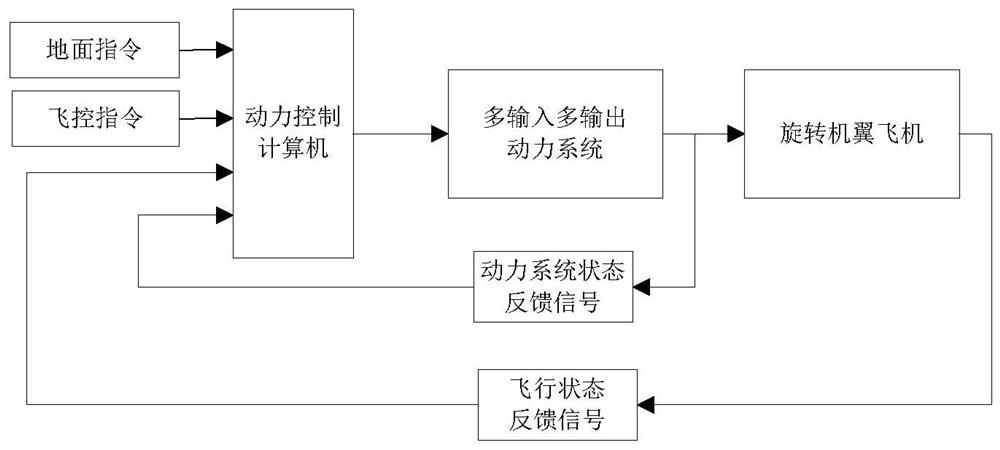
The present invention proposes a multi-input multi-output power system and control method for a rotary-wing aircraft, including a rotor, a propeller providing power for forward flight, and an active power source for providing power to the propeller during the fixed-wing flight mode stage of the rotary-wing aircraft , the auxiliary power source that provides power to the rotor together with the main power source during the vertical take-off and landing phase of the rotary wing aircraft, and the front transmission mechanism from the main power source to the propeller and the main transmission mechanism from the main power source, the auxiliary power source to the rotor . The present invention adopts multiple power sources, such as a fuel engine and an electric motor, through the transmission device of the power system to carry out power confluence and distribution of multiple power sources, and according to different flight stages of the rotary wing aircraft, different control strategies are used to redistribute the power , to form a comprehensive power system with multi-input power confluence and diversion and realize multi-output requirements through control distribution, so as to not only meet the high power demand of the rotor mode, but also make the power system work in the optimal economic state in the fixed-wing mode.

Description

technical field [0001] The invention relates to the technical field of rotary wing aircraft, in particular to the power matching technology of medium and large rotary wing aircraft, in particular to a multi-input and multiple output power system and control method for rotary wing aircraft. Background technique [0002] Rotary wing aircraft is a new type of unmanned aircraft that has both the vertical take-off and landing performance of a helicopter and the high-speed cruise performance of a fixed-wing aircraft. The patent number is ZL201110213680.1, and the Chinese patent titled "A Rotary Wing Aircraft with Variable Flight Mode" is a typical model. The aircraft has a three-plane aerodynamic layout. Among them, in the helicopter flight mode, the main wing can rotate as a rotor to provide the required pulling force for the aircraft. At the same time, when the aircraft has a certain flight speed, it can be locked as a fixed wing to achieve high-efficiency fixed-wing flight. T...

Claims


Application Information

Patent Timeline
Patent Type & Authority Patents(China)
IPC IPC(8): B64D27/02B64D35/02B64D35/04
Inventor 高正红那洋张珊珊冯尚龙何澳
Owner 南京灵龙旋翼无人机系统研究院有限公司
Learn More