Novel dual-glass photovoltaic module

A dual-glass photovoltaic and module technology, applied in the field of solar energy, can solve the problems of cell mismatch, reduce the output power of modules, limited number of bypass diodes, etc., to reduce the incidence of failures, ensure reliability and life, and ensure maximum The effect of output power

Pending Publication Date: 2017-07-04
WORLDWIDE ENERGY & MFG NANTONG
0 Cites 3 Cited by

AI-Extracted Technical Summary

Problems solved by technology

Generally, double-glass photovoltaic modules are installed in solar smart windows, solar gazebos, glass building roofs, and glass curtain walls, etc. The larger junction boxes are installed on the back of the modules, which hinders the aesthetics of the modules and affects the light transmittance of the modules.
The junction box is installed on the back of the module, and its poor heat dis...

Method used

[0020] The present invention can embed the bypass diodes inside the assembly by setting the grooves for placing the bypass diodes on the front of the rear glass, and the number and positions of the bypass diodes can be arbitrarily set according to actual needs, so the total number of The fixed solar cells are divided into more solar cell strings. Even if the solar cells in the module are shaded, the impact of this shading is very small, so the module still has a large output power in this case . Since the bypass diode is installed inside the module, and the bypass diode is arranged in the non-battery a...

Abstract

The invention discloses a novel dual-glass photovoltaic module. The novel dual-glass photovoltaic module comprises front glass, a front EVA adhesive film, solar cell pieces, a rear EVA adhesive film and rear glass, wherein a plurality of grooves are formed in a front surface of the rear glass, a bypass diode is arranged in each groove, the bypass diode is arranged on a non-solar cell piece region, a cable and a connector are arranged on a back surface of the rear glass, the solar cell pieces are connected in series to form a plurality of solar cell strings by using soldering strips, a plurality of convergence belts are arranged at an upper part and a lower part of the module and are used for connecting the solar cell strings, each bypass diode is connected in series and in parallel with a corresponding solar cell, and a positive electrode and a negative electrode of the bypass diode are respectively connected with a negative electrode and a positive electrode of the corresponding solar cell string. By forming the grooves in the rear glass, many bypass diodes are arranged in the module, optimal protection function is provided for the module, and maximum output power of the module is ensured; moreover, a junction box is omitted, and the module cost is reduced; and meanwhile, the reliability of the module can also be improved.

Application Domain

Technology Topic

Image

  • Novel dual-glass photovoltaic module
  • Novel dual-glass photovoltaic module

Examples

  • Experimental program(1)

Example Embodiment

[0017] In order to further understand the technical features and content of the present invention, the following description is made in conjunction with the accompanying drawings.
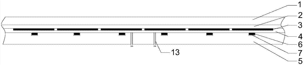
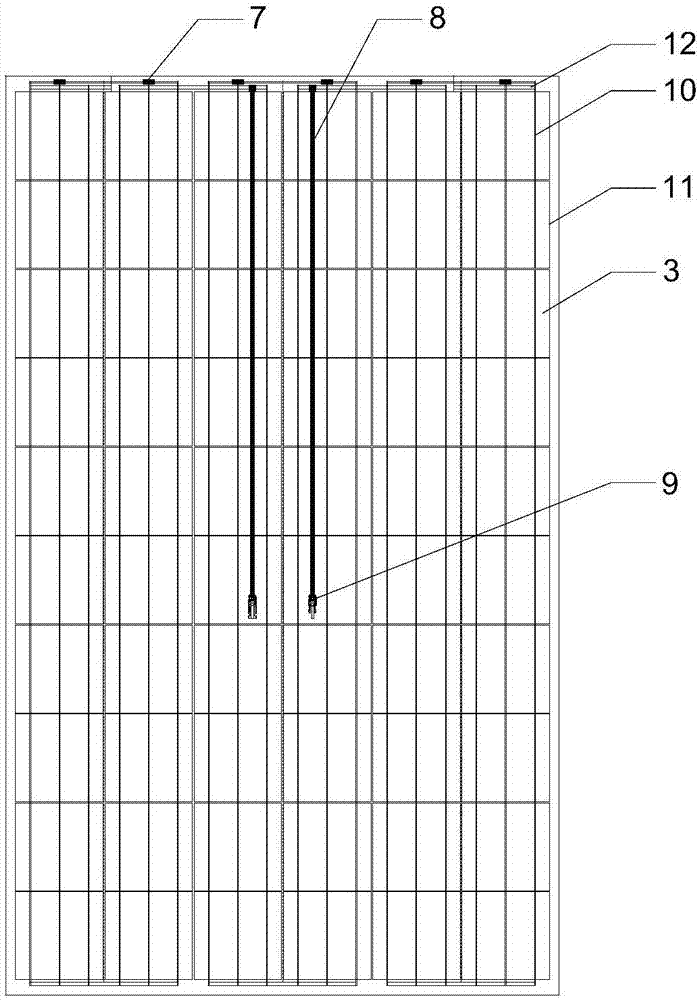
[0018] Such as figure 1 with figure 2 As shown, a new type of double-glass photovoltaic module includes a front glass 1, a front EVA film 2, a solar cell 3, a rear EVA film 4, and a rear glass 5. The rear glass is provided with There are a number of grooves 6, each of which is provided with a bypass diode 7, and a cable 8 and a connector 9 are provided on the back of the rear glass.
[0019] The solar cell sheet uses solder ribbon 10 to form a plurality of solar cell strings 11 in series, and a plurality of bus ribbons 12 are respectively used on the upper and lower parts of the module to connect the solar cell strings in series. Each bypass diode arranged in the rear glass groove is connected in parallel with the corresponding solar cell string, the anode of the bypass diode is connected to the cathode of the solar cell string, and the cathode of the bypass diode is connected to the anode of the solar cell string. When the solar cells work normally, the bypass diode is in a reverse bias state; and when part of the solar cells in the solar cell string connected in parallel with the bypass diode are blocked, in order to prevent these cells from overheating and damage due to the hot spot effect, connect them in parallel at this time The bypass diode will be forward-conducting, so that the current flowing through the shaded cell is shunted by the bypass diode. The bypass diode is preferably a chip Schottky diode. The rear glass is provided with two through holes 13 from which the two bus bands after each solar cell string are connected in series are led out to the back of the rear glass and connected with external cables.
[0020] In the present invention, by providing a groove for placing bypass diodes on the front side of the rear glass, the bypass diodes can be embedded in the component, and the number and positions of the bypass diodes can be set arbitrarily according to actual needs, so the total number of solar energy can be fixed. The cells are divided into more solar cell strings. Even if the solar cells in the module are shaded by shadows, the impact of such shading is small, so the module still has a large output power in this case. Since the bypass diode is installed inside the module, and the bypass diode is installed in the non-cell area, the junction box used on the back of the conventional module can be removed, which reduces the cost of the module to a certain extent. At the same time, the heat generated by the junction box causes the loss of the cell. With this kind of influence no longer exists, indirectly increase the output power of the module. In addition, the double-glass component has a lower junction temperature for the bypass diode by virtue of its good heat dissipation capacity, which ensures the reliability and life of the bypass diode, reduces the incidence of failures, and improves the reliability of the component.
[0021] The embodiments of the present invention are not limited to this. According to the above content of the present invention, according to the prior art and knowledge in the field, combined with the basic idea and technology of the present invention, the mode and position of the built-in bypass diode can be adjusted. These changes or Improvements should fall within the scope of protection of this patent.

PUM

no PUM

Description & Claims & Application Information

We can also present the details of the Description, Claims and Application information to help users get a comprehensive understanding of the technical details of the patent, such as background art, summary of invention, brief description of drawings, description of embodiments, and other original content. On the other hand, users can also determine the specific scope of protection of the technology through the list of claims; as well as understand the changes in the life cycle of the technology with the presentation of the patent timeline. Login to view more.

Similar technology patents

Inorganic phosphorescent article and method for making same

InactiveUS20100285284A1Pronounced and sustained phosphorescent effectImprove aestheticsDecorative surface effectsDuplicating/marking methodsZinc sulfideEmergency light
Owner:LACOURSE BRIAN C

Classification and recommendation of technical efficacy words

Why Eureka
Try Eureka