
Mask device and evaporation method

A mask and vapor deposition technology, applied in the field of mask device and vapor deposition, can solve the problems such as the inability to cope with the clamping of the netting equipment, the increase of wrinkles, and the decrease of the qualified rate of the netting.

Active Publication Date: 2019-06-21
BOE TECH GRP CO LTD +1
View PDF5 Cites 10 Cited by
  • Summary
  • Abstract
  • Description
  • Claims
  • Application Information

AI Technical Summary

Problems solved by technology

[0003] At present, the evaporation of large-size masks has the following problems: manufacturers cannot produce corresponding wide-width masks; the size of masks increases, resulting in increased sagging in the middle area, increased wrinkles, and a decrease in the qualified rate of opening; The size of the mask plate increases, and the jigs of the stretching equipment cannot correspond, and it is impossible to rely on the existing equipment to complete the stretching

Method used


Image

  • Mask device and evaporation method
  • Mask device and evaporation method
  • Mask device and evaporation method

Examples


Embodiment 1

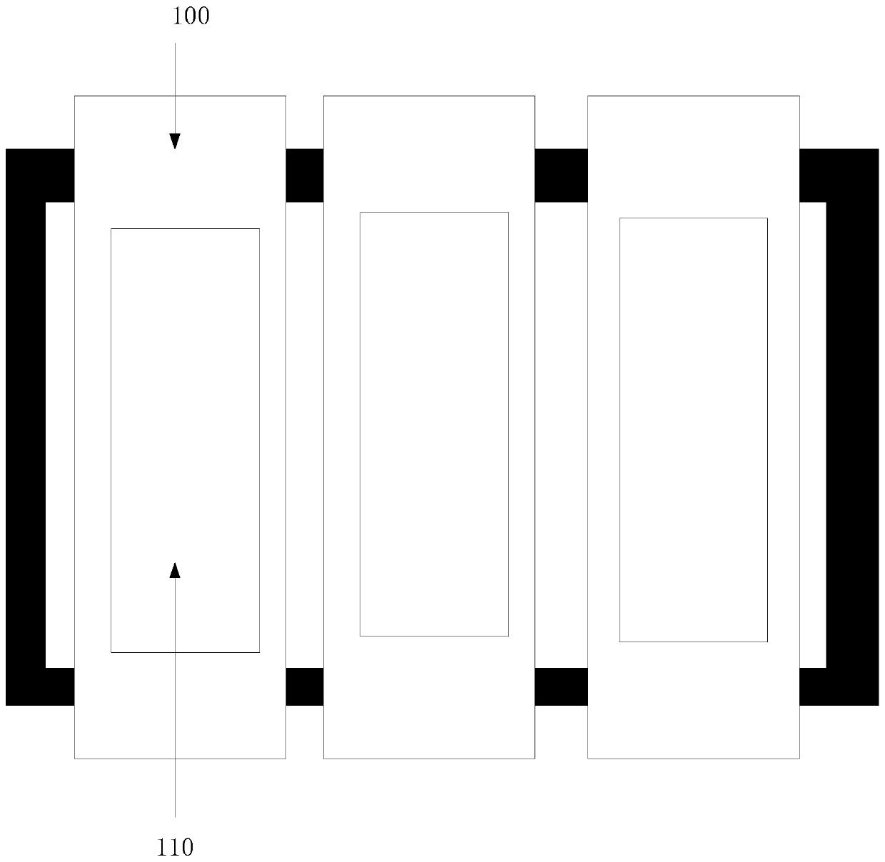
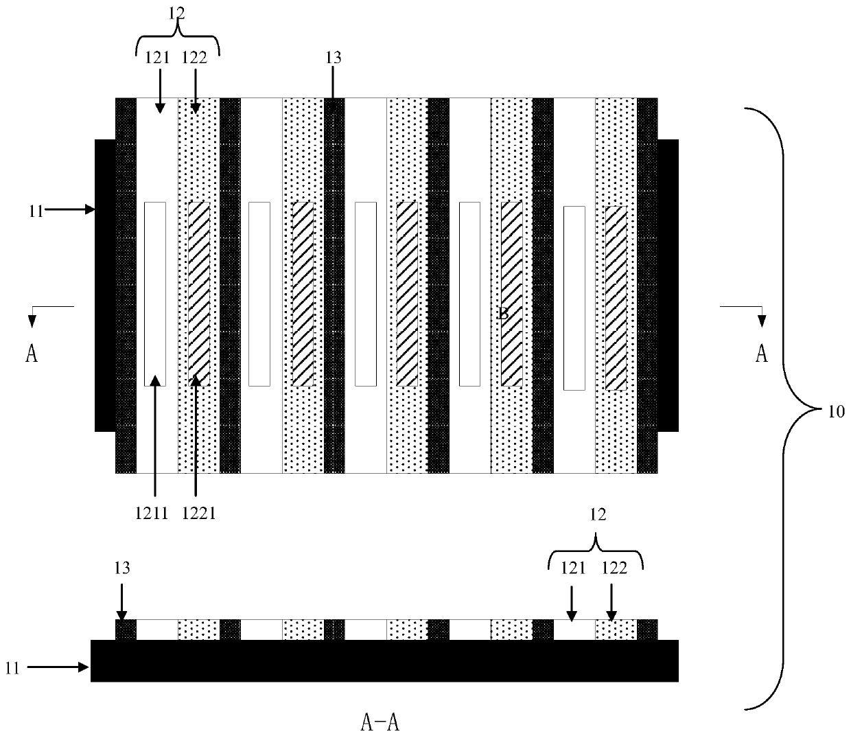
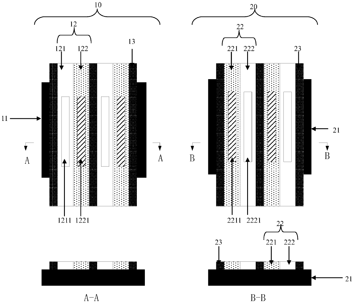
[0042] refer to figure 2 , to provide a mask device, comprising: a first mask 10; the first mask comprises a first frame 11, and a first mask strip 12 and a first mask strip 12 and a first mask are arranged side by side on the first frame 11 Blocking strips 13, the first masking strips 12 and the first blocking strips 13 are arranged at intervals;

[0043] The first mask strip 12 includes: a first sub-mask strip 121 and a second sub-mask strip 122 spliced ​​with each other; a first hollow area 1211 is provided on the first sub-mask strip 121 .

[0044] Wherein, the thickness of the middle region 1221 of the second sub-mask strip 122 is smaller than the thickness of the edge region.

[0045] In a specific implementation, the thickness of the middle region 1221 of the second sub-mask strip 122 is 0.4-0.6 times the thickness of the edge region.

[0046] In the embodiment of the present invention, the middle area is set relatively thin, which can prevent the middle area of ​​th...

Embodiment 2

[0064] refer to Figure 4 , an embodiment of the present invention provides an evaporation method, including:

[0065] Step 201, aligning the evaporation object with the first mask; defining a region to be evaporated on the evaporation object, and aligning the first hollowed out region with the first part of the region to be evaporated .

[0066] In the embodiment of the present invention, the first mask plate and the vapor deposition object are aligned through the alignment marks on the first shielding layer.

[0067] In the embodiment of the present invention, the evaporation target includes a display panel, and the area to be evaporated is the pixel defining layer on the glass substrate in the display panel.

[0068] Wherein, the first mask plate is placed on the evaporation object, the first hollow area corresponds to a part of the area to be evaporated, and the second sub-mask bars block the rest of the area to be evaporated.

[0069] In a specific implementation, the ...


PUM


Abstract

The invention provides a mask device and an evaporation method. The mask device comprises a first mask plate, and the first mask plate comprises a first frame, and a first mask strip and a first blocking strip which are arranged on the first frame side by side; the first mask strip and the first blocking strip are arranged at intervals; the first mask strip comprises a first sub mask strip and a second sub mask strip which are spliced; and a first hollowed-out region is arranged on the first sub mask strip. According to the mask device, the mask strip is divided into the two sub mask strips, netting difficulty is reduced, and preparation of a variable-amplitude mask plate is achieved; and besides, when the size of the mask plate is increased, the situation that the droop amount of the middle region of the mask strip is increased as the mask strip is too wide is avoided, and evaporation precision of the variable-amplitude mask plate is improved.

Description

technical field [0001] The present invention relates to the field of display technology, and in particular, to a mask device and an evaporation method. Background technique [0002] In the production process of display panels, metal masks are required for the evaporation of luminescent materials. With the increasing market demand for large-size and vehicle-mounted displays, it is imminent to achieve high-precision metal mask evaporation for large-size products. [0003] At present, the evaporation of large-size masks has the following problems: manufacturers cannot make corresponding wide masks; mask size increases, resulting in increased sagging in the middle area, increased wrinkles, and reduced screen pass rate; The size of the mask plate increases, and the opening equipment fixture cannot correspond, and the existing equipment cannot be used to complete the opening. SUMMARY OF THE INVENTION [0004] The present invention provides a mask device to solve at least one of...

Claims


Application Information

Patent Timeline
IPC IPC(8): C23C14/04C23C14/24
CPCC23C14/042H10K71/166C23C14/24
Inventor 嵇凤丽梁少端杨晓宇段芳芳罗昶
Owner BOE TECH GRP CO LTD
Learn More