Fence intensifier and fence intensifying method

A technology of intensifiers and fences, applied in the direction of fences, building types, buildings, etc., can solve the problems of increasing the probability of shaking influence and the labor of tensioning tools, and achieves the effect of easy control and prevention of scratching fingers.

Pending Publication Date: 2019-06-21
固耐特(苏州)智能科技有限公司
View PDF13 Cites 1 Cited by
  • Summary
  • Abstract
  • Description
  • Claims
  • Application Information

AI Technical Summary

Problems solved by technology

[0005] One of the purposes of the present invention is to solve the problem that the tensioning tool in the prior art will cause effort and increase the probability of shaking

Method used


Image

  • Fence intensifier and fence intensifying method
  • Fence intensifier and fence intensifying method
  • Fence intensifier and fence intensifying method

Examples


Embodiment 1

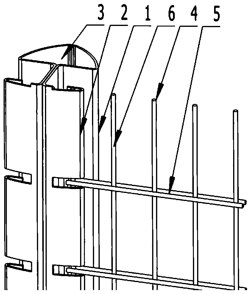
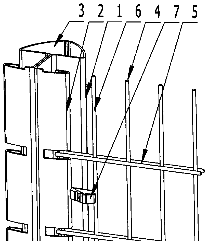
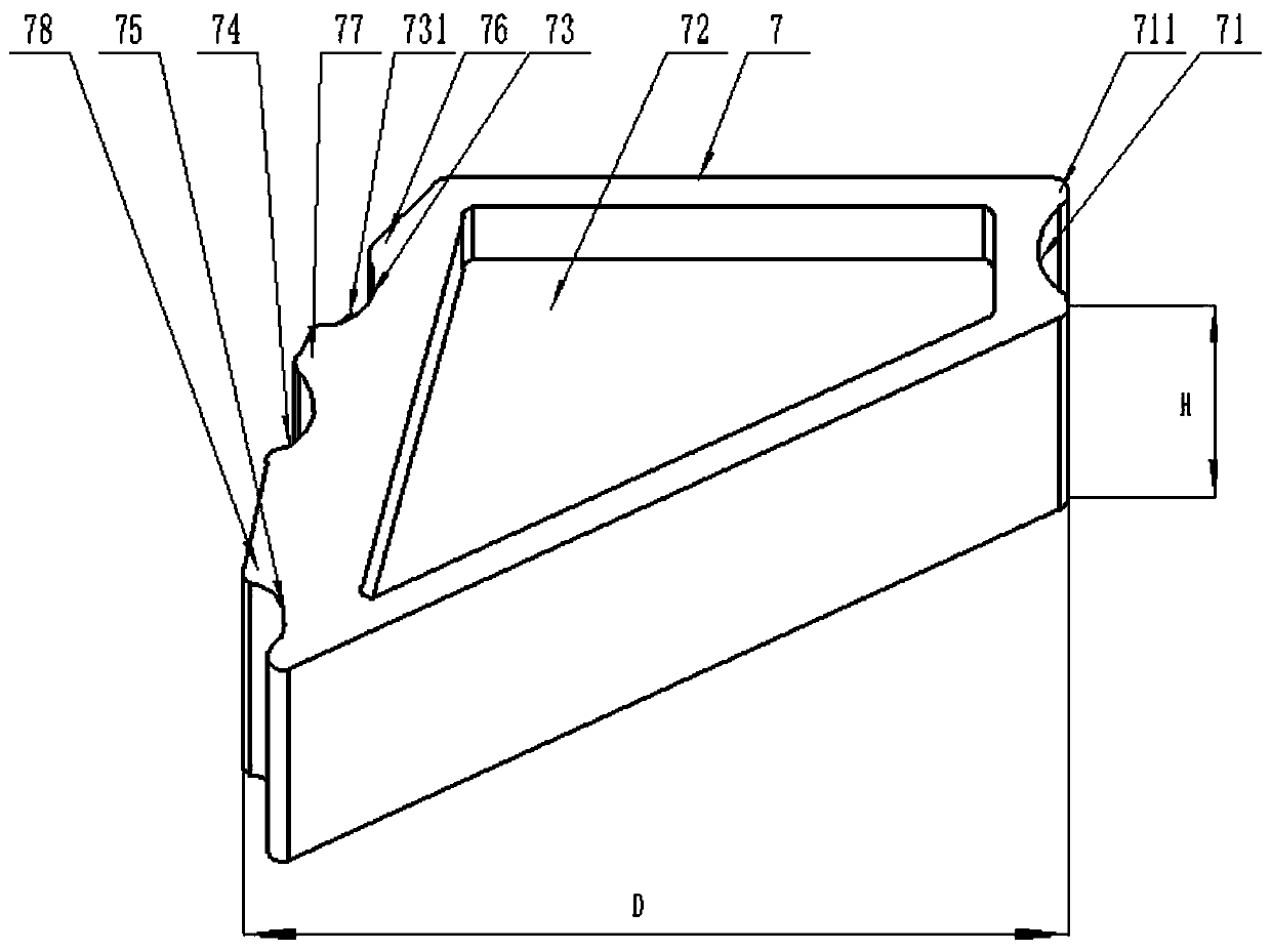
[0059] A fence enhancer such as image 3 As shown, during the installation process of the fence, both the column 1 and the mesh 3 installed on the column 1 are tensioned along the transverse direction D, and the column 1 has a hook 2 extending along the longitudinal direction H, and the fence mesh 3 It is composed of several horizontal wires 5 extending along the transverse direction D and several longitudinal wires 6 extending along the longitudinal direction H, including: the installation body 7, the installation body 7 is installed on the longitudinal wires 6 or on the horizontal wires 5 or on the column 1 On the hook part 2, the length of the installation body 7 in the longitudinal H direction is smaller than the gap between the horizontal wires 5 in the mesh sheet 3. The installation body 7 includes: abutting groove 71, first recess 73, first top 76, second top 77. The force applying part 72. The pressing groove 71 has a pressing space, and the pressing space is used to ...

Embodiment 2

[0085] A fence has the fence enhancer of the first embodiment above.

Embodiment 3

[0087] A fence installation method, comprising the following steps:

[0088] Hooking, dragging the longitudinal wire or the horizontal wire part of the mesh, and hooking the longitudinal wire in the hook part of the column;

[0089] The fence installation method also has the steps of the fence strengthening method in the first embodiment above.


PUM


Abstract

The invention discloses a fence intensifier, and relates to the technical field of fence tools. The fence intensifier comprises an abutting groove 71, a first concave part 73, a first top 76, a secondtop 77 and a force application part 72. The abutting groove 71 and the first concave part 73 are not arranged on a same transverse D center line; a longitudinal wire 6 is extruded towards the direction of the joint of the first concave part 73 and the second top 77, so that the part, supporting the longitudinal wire 6, of the first concave part 73 is changed, and furthermore, the acting force ofthe longitudinal wire 6 only concentrates on one side direction of the first concave part 73, the acting force of the longitudinal wire 6 is prevented from being concentrated on the edge portion of the first concave part 73 intersecting with the center line of the first concave portion 73 (at the moment, the longitudinal wire 6 has two movable directions under the action of external force), thus the longitudinal wire 6 can slide along the edge portion of the first concave part 73 under the action of the external force, and the longitudinal wire 6 shakes.

Description

technical field [0001] The invention relates to the technical field of fence tools, in particular to a fence enhancer. Background technique [0002] The fence is an energy-absorbing structure that absorbs collision energy through self-deformation or object climbing. Fences are widely used in the maintenance of municipal engineering, transportation, communities, ports, airports, storage and other areas. These products are becoming more and more mature and become an important branch of the building materials industry. The scale of the industry continues to expand and the styles continue to increase. [0003] Currently, if figure 1 As shown, the fence is composed of a column 1 and a mesh 4. The column 1 has a filling space 3 extending longitudinally and a hook 2 arranged longitudinally along the filling space 3. The mesh 4 is composed of several horizontal wires extending transversely. 5 and several longitudinal wires 6 extending longitudinally. When installing the fence, th...

Claims


Application Information

Patent Timeline
Patent Type & Authority Applications(China)
IPC IPC(8): E04H17/14E04H17/20E04H17/26
Inventor 徐律吴海
Owner 固耐特(苏州)智能科技有限公司
Why Eureka
Try Eureka