Single-stage axial-flow high-pressure compressor with asymmetric end walls

A compressor, asymmetric technology, applied in the direction of mechanical equipment, non-variable pumps, machines/engines, etc., can solve the problem of secondary flow loss increase

Active Publication Date: 2021-10-26
BEIHANG (SICHUAN) WESTERN INT INNOVATION PORT TECH CO LTD
View PDF10 Cites 0 Cited by
  • Summary
  • Abstract
  • Description
  • Claims
  • Application Information

AI Technical Summary

Problems solved by technology

However, because there is still a transverse pressure gradient in the compressor channel, the channel vortex is prone to corner separation when it flows from the pressure surface of the blade to the suction surface, resulting in an increase in secondary flow loss

Method used


Image

  • Single-stage axial-flow high-pressure compressor with asymmetric end walls
  • Single-stage axial-flow high-pressure compressor with asymmetric end walls
  • Single-stage axial-flow high-pressure compressor with asymmetric end walls

Examples


Embodiment Construction

[0024] The present disclosure will be further described in detail below with reference to the drawings and embodiments. It can be understood that the specific implementation manners described here are only used to explain relevant content, rather than to limit the present disclosure. It should also be noted that, for ease of description, only parts related to the present disclosure are shown in the drawings.

[0025] It should be noted that, in the case of no conflict, the implementation modes and the features in the implementation modes in the present disclosure can be combined with each other. The present disclosure will be described in detail below with reference to the drawings and embodiments.

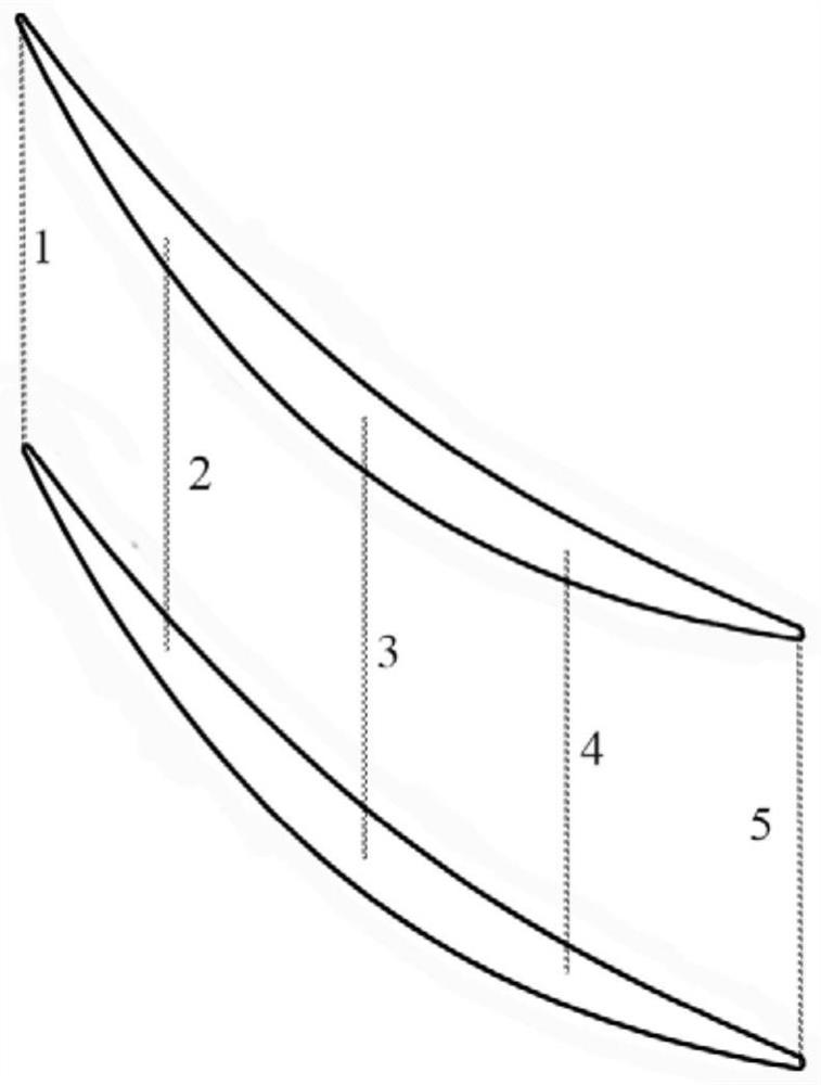
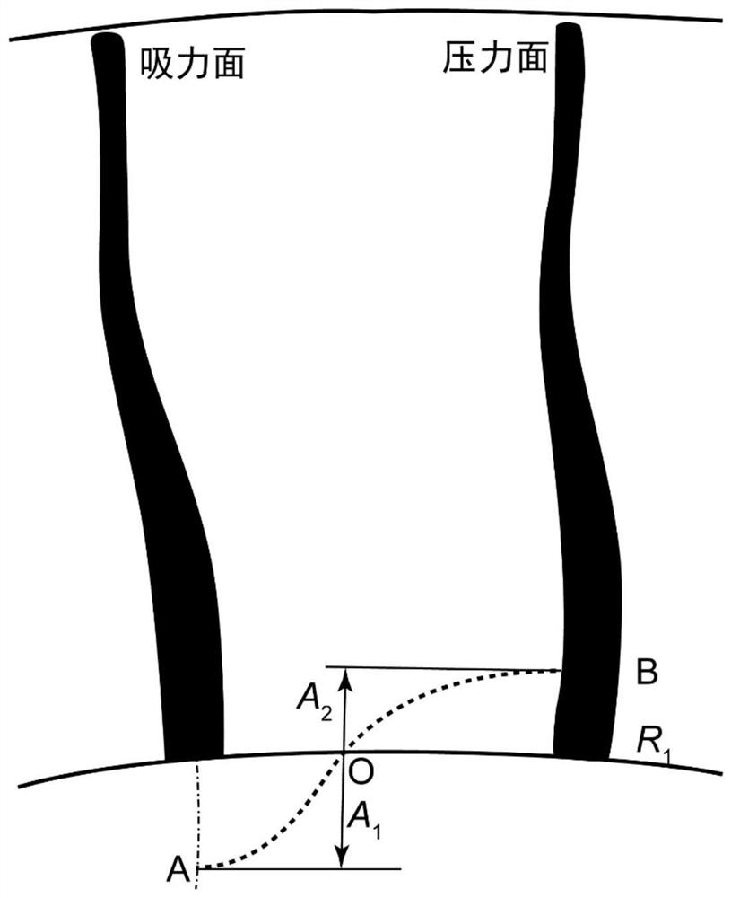
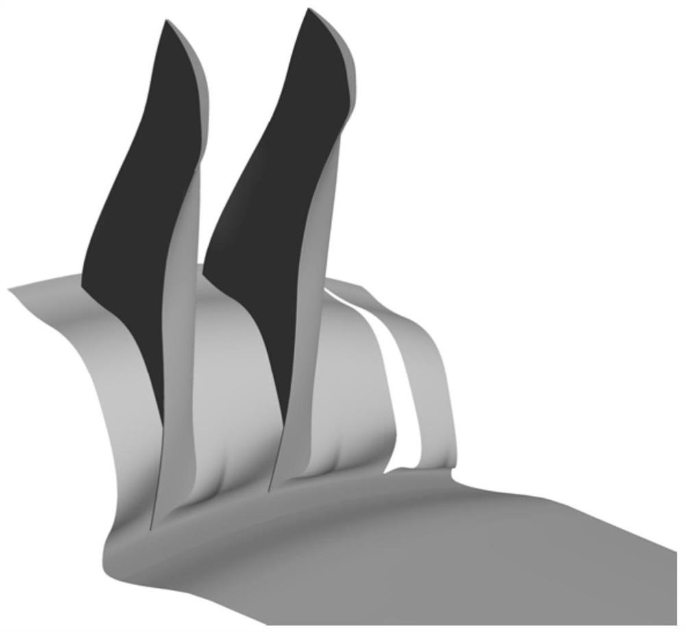
[0026] In at least one embodiment of the present disclosure, the present disclosure provides a single-stage axial flow high-pressure compressor comprising a hub having asymmetric end walls obtained by sweeping a profile line built in a blade passage , which is a non-axisymmetric...


PUM


Abstract

The present disclosure provides a single-stage axial-flow high-pressure compressor comprising a hub having an asymmetric end wall obtained by sweeping a profile line built in a blade channel, the profile line being a non-axisymmetric curve, and constructed using trigonometric functions.

Description

technical field [0001] The present disclosure relates to a single-stage axial-flow high-pressure compressor. Background technique [0002] With the great development of aviation technology, researchers are also exploring the limits of the performance of engine components. As one of the core components of the engine, the design and optimization of the compressor is a topic that researchers continue to pay attention to. However, as the stage pressure ratio of the axial flow compressor increases, the compressor continues to develop in the direction of low aspect ratio and high load. Separation and clogging become more prominent, resulting in a decrease in compressor efficiency and, in severe cases, a rotational stall of the compressor. Therefore, taking appropriate measures to reduce flow separation and blockage in the compressor is an effective way to increase the load of the compressor. [0003] For the boundary layer in the end zone and flow separation and clogging, bette...

Claims


Application Information

Patent Timeline
Patent Type & Authority Patents(China)
IPC IPC(8): F04D29/38F04D29/66
Inventor 李志平潘天宇李秋实张亚飞
Owner BEIHANG (SICHUAN) WESTERN INT INNOVATION PORT TECH CO LTD
Why Eureka
Try Eureka