Hydraulic damper

A damper and hydraulic technology, applied in the field of hydraulic dampers, can solve the problems of low filling and draining efficiency of hydraulic dampers, long filling and draining time, etc., and shorten the loading time and unloading time , shorten the filling time and draining time, and improve the effect of braking response speed

Pending Publication Date: 2019-06-21
SHENZHEN CYCLONE FLUID TECH CO LTD
View PDF0 Cites 0 Cited by
  • Summary
  • Abstract
  • Description
  • Claims
  • Application Information

AI Technical Summary

Problems solved by technology

Since the existing damper uses different pipelines for liquid filling and draining, when increasing the air pressure g above the liquid storage tank e to fill the hydraulic damper, it is difficult to avoid the hydraulic damper draining at the same time, when reducing the liquid storage When the air pressure g above the box e drains the hydraulic damper, it is difficult to avoid filling the hydraulic damper at the same time, which makes the filling and draining efficiency of the hydraulic damper not high, and the filling and draining time is relatively long long

Method used


Image

  • Hydraulic damper
  • Hydraulic damper
  • Hydraulic damper

Examples


Embodiment Construction

[0025] The present application will be described in further detail below through specific embodiments in conjunction with the accompanying drawings.

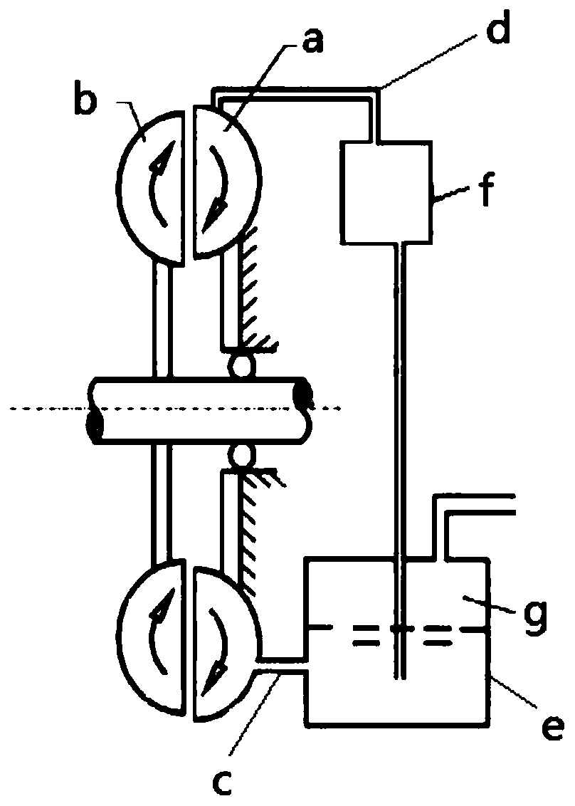
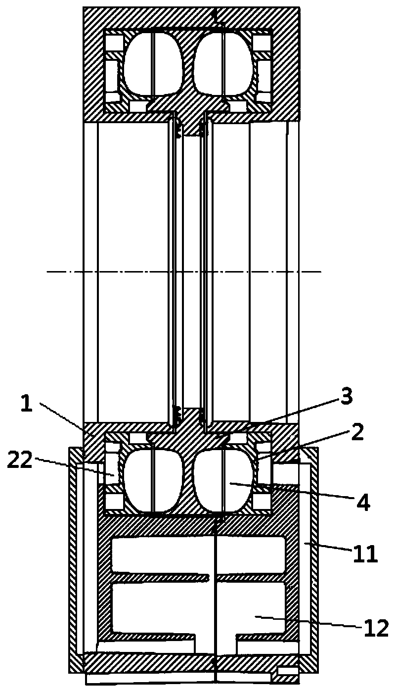
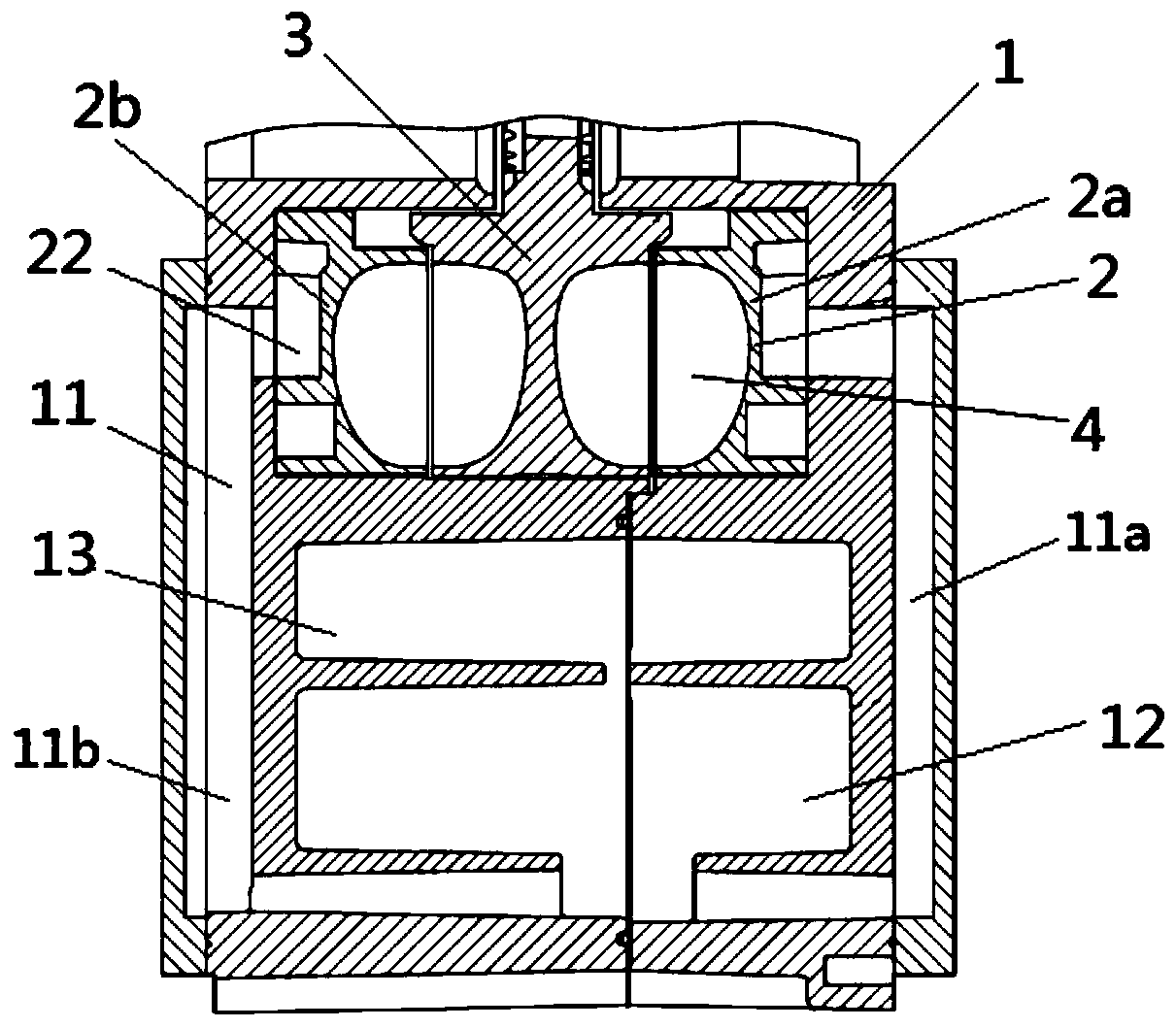
[0026] Such as Figure 2-5 As shown, a hydraulic damper includes a housing 1, a stator 2 and a rotor 3, the stator 2 and the rotor 3 are installed inside the housing, the back of the stator 2 is fixed on the housing 1, and the rotor 3 is externally connected to the rotating shaft, rotating The shaft will drive the rotor 3 to rotate. The front of the stator 2 and the rotor 3 form a working chamber 4, which is used to accommodate working fluid. Such as image 3 and Figure 5 As shown, the stator 2 has a liquid filling and draining hole 21 through the front and back of the stator 2. The opening of the liquid filling and draining hole 21 in the front direction of the stator 2 communicates with the working chamber 4, and the housing 1 has a liquid flow channel. 11 and the liquid storage tank 12, one end of the liquid flow channel...


PUM


Abstract

The invention discloses a hydraulic damper. The hydraulic damper comprises a shell, a stator and a rotor, wherein the stator and the rotor are both located in the shell. The back face of the stator isfixed on the shell, the front surface of the stator and the rotor form a working cavity, and the working cavity is used for containing working liquid. The stator is provided with liquid filling and liquid discharging holes which penetrate through the front surface and the back surface of the stator, a liquid flow channel and a liquid storage tank are arranged in the shell, one end of the liquid flow channel communicates with the portions, in the back surface of the stator, of the liquid filling and liquid discharge holes, and the other end of the liquid flow channel is connected with the lower end of the liquid storage tank. According to the hydraulic damper disclosed by the invention, the same channel is adopted for the liquid filling and liquid discharging of the hydraulic damper, the liquid filling time and the liquid discharging time can be effectively shortened, and the performance of the hydraulic damper can be remarkably improved.

Description

technical field [0001] The present application relates to the technical field of dampers, in particular to a hydraulic damper. Background technique [0002] Hydraulic damper is an auxiliary braking device for automobiles, which is mainly used in large passenger cars, urban public transport vehicles, heavy trucks, military vehicles and trailers. into a trend. [0003] The structure of the hydraulic damper installed on different vehicles is roughly the same, and generally consists of a stator, a rotor, a working chamber, an input shaft, a heat exchanger, a liquid storage tank and a housing. When the damper is working, the compressed air enters the liquid storage tank through the solenoid valve, and the working fluid in the liquid storage tank is pressed into the damper through the liquid circuit, and the damper starts to work, and the rotor drives the working fluid to rotate around the axis, and at the same time, the working fluid moves along the blades. The directional move...

Claims


Application Information

Patent Timeline
Patent Type & Authority Applications(China)
IPC IPC(8): F16D57/02
Inventor 李天维雷光新高祥民方力宏
Owner SHENZHEN CYCLONE FLUID TECH CO LTD
Why Eureka
Try Eureka