Supercharge Your Innovation With Domain-Expert AI Agents!

Box-type ceramic three-way valve with flow channel being conveniently switched on line

A three-way valve and box-type technology, applied in the field of pneumatic conveying system and box-type ceramic three-way valve, can solve the problems of troublesome operation of online switching flow channel, inability to realize online switching flow channel, stuck or stuck in the sealing position, etc. , to achieve the effect of guaranteeing service life, flexible adjustment and online switching, avoiding jamming or jamming

Pending Publication Date: 2019-06-21
郑州鼎盛新技术有限公司
View PDF0 Cites 0 Cited by
  • Summary
  • Abstract
  • Description
  • Claims
  • Application Information

AI Technical Summary

Problems solved by technology

At present, this kind of traditional three-way structure valve is a structure in which three holes are directly connected. Although it has the advantage of occupying a small space, it also has disadvantages: (1) It is impossible to switch flow channels online or switch flow channels online. trouble
(2) When the material flow direction changes, the flow resistance increases, the valve core wears more seriously in the bend section, and the service life is very short
(3) The sealing position is often jammed or stuck due to slag inclusion or other reasons

Method used


Image

  • Box-type ceramic three-way valve with flow channel being conveniently switched on line
  • Box-type ceramic three-way valve with flow channel being conveniently switched on line

Examples


Embodiment Construction

[0015] The present invention will be further described below in conjunction with the accompanying drawings.

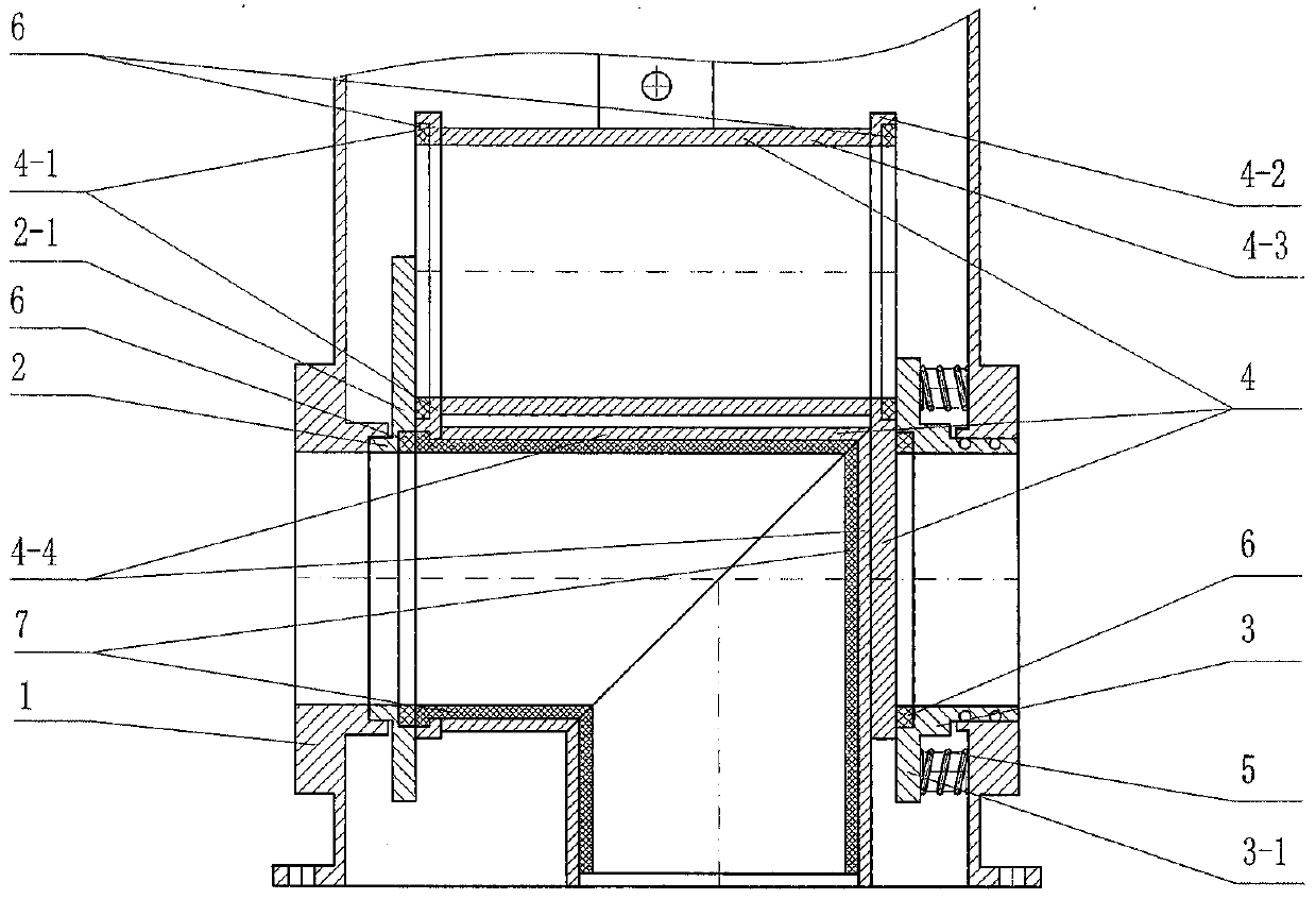
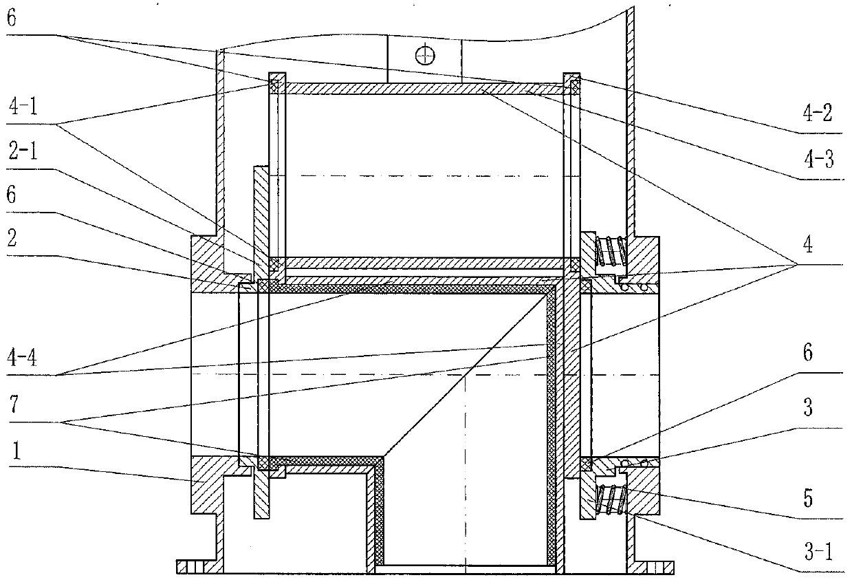
[0016] Such as figure 1 As shown, a box-type ceramic three-way valve of the present invention that facilitates online switching of flow channels includes a box-type valve body (1), which is embedded in the two proximal ends of the box-type valve body (1) flow channel cavity in a coaxial manner. 1. The fixed valve seat (2) and the elastic valve seat (3) in the form of a flange sleeve are stuck on the flange plate I (2-1) of the fixed valve seat (2) and the elastic valve seat (3). The movable spool (4) that can slide up and down between the blue plates II (3-1) (according to the switching needs of the material flow direction, the actuator connected to the movable spool (4) is controlled to drive the movable spool (4) along the The track consisting of the flange plate Ⅰ (2-1) of the fixed valve seat (2) and the flange plate Ⅱ (3-1) of the elastic valve seat (3) moves up ...


PUM


Abstract

The invention discloses a box-type ceramic three-way valve with a flow channel being conveniently switched on line, and relates to the field of valves. The box-type ceramic three-way valve comprises abox-type valve body, a fixed valve seat, an elastic valve seat, a movable valve element and a spring, wherein the fixed valve seat and the elastic valve seat are embedded at the two near ends of a flow channel cavity of the box-type valve body in a coaxial mode and are each of a flange sleeve structure, the movable valve element is placed between a flange plate I of the fixed valve seat and a flange plate II of the elastic valve seat in a clamped mode and can slide up and down, and the spring is pressed between the flange plate II and the inner wall of the box-type valve body; the movable valve element is constituted by through pipes and a 90-degree bend, wherein the two ends of the through pipes are correspondingly connected with the near end faces of a flange plate III and a flange plate IV which are parallel mutually, and the through pipes are arranged in an up-down layering mode; and ceramic rings are embedded on the near end faces of the flange plate I and the flange plate II andthe far end faces of the flange plate III and the flange plate IV correspondingly, and an overall ceramic pipe is mounted in the mode of being closely attached to the inner wall of the 90-degree bend. The box-type ceramic three-way valve can achieve flexible adjusting and on-line switching of the material flowing direction, and has the advantages that the box-type ceramic three-way valve is resistant to abrasion and corrosion, good in sealing effect and long in service life, and jamming or sticking of the sealing position is avoided.

Description

technical field [0001] The invention belongs to the technical field of valves, and in particular relates to a box-type ceramic three-way valve that is convenient for switching flow channels online, and is especially suitable for installation in a pneumatic conveying system that needs to convey dry powdery materials to different directions and places. Background technique [0002] In the pneumatic conveying system of dry powdery materials, it is sometimes necessary to transport dry powdery materials to different directions and places, which requires the installation of a valve with a three-way structure to meet the needs of use: that is, this valve needs to have a Feed port, two discharge ports, the material can be transported along the direction of the main pipeline through the feed port and one of the coaxial discharge ports, or the material can be changed through the feed port and the other vertically downward discharge port. After the flow direction, it is transported dir...

Claims


Application Information

Patent Timeline
IPC IPC(8): F16K11/065F16K3/314F16K3/30
Inventor 马俊峰邵毅
Owner 郑州鼎盛新技术有限公司
Features
  • R&D
  • Intellectual Property
  • Life Sciences
  • Materials
  • Tech Scout
  • Unparalleled Data Quality
  • Higher Quality Content
  • 60% Fewer Hallucinations
Learn More