Voltage-controlled-oscillator circuit

A voltage-controlled oscillator and circuit technology, applied in the direction of instruments, electrical components, automatic power control, etc., can solve problems such as infeasibility and difficulty with two VCOs

Pending Publication Date: 2019-06-21
NXP USA INC
View PDF0 Cites 0 Cited by
  • Summary
  • Abstract
  • Description
  • Claims
  • Application Information

AI Technical Summary

Problems solved by technology

[0003] In some applications where it is desirable to be able to switch from one operating band to another in real time, it is difficult or not feasible to use two VCOs due to timing and frequency alignment issues

Method used


Image

  • Voltage-controlled-oscillator circuit
  • Voltage-controlled-oscillator circuit
  • Voltage-controlled-oscillator circuit

Examples


Embodiment Construction

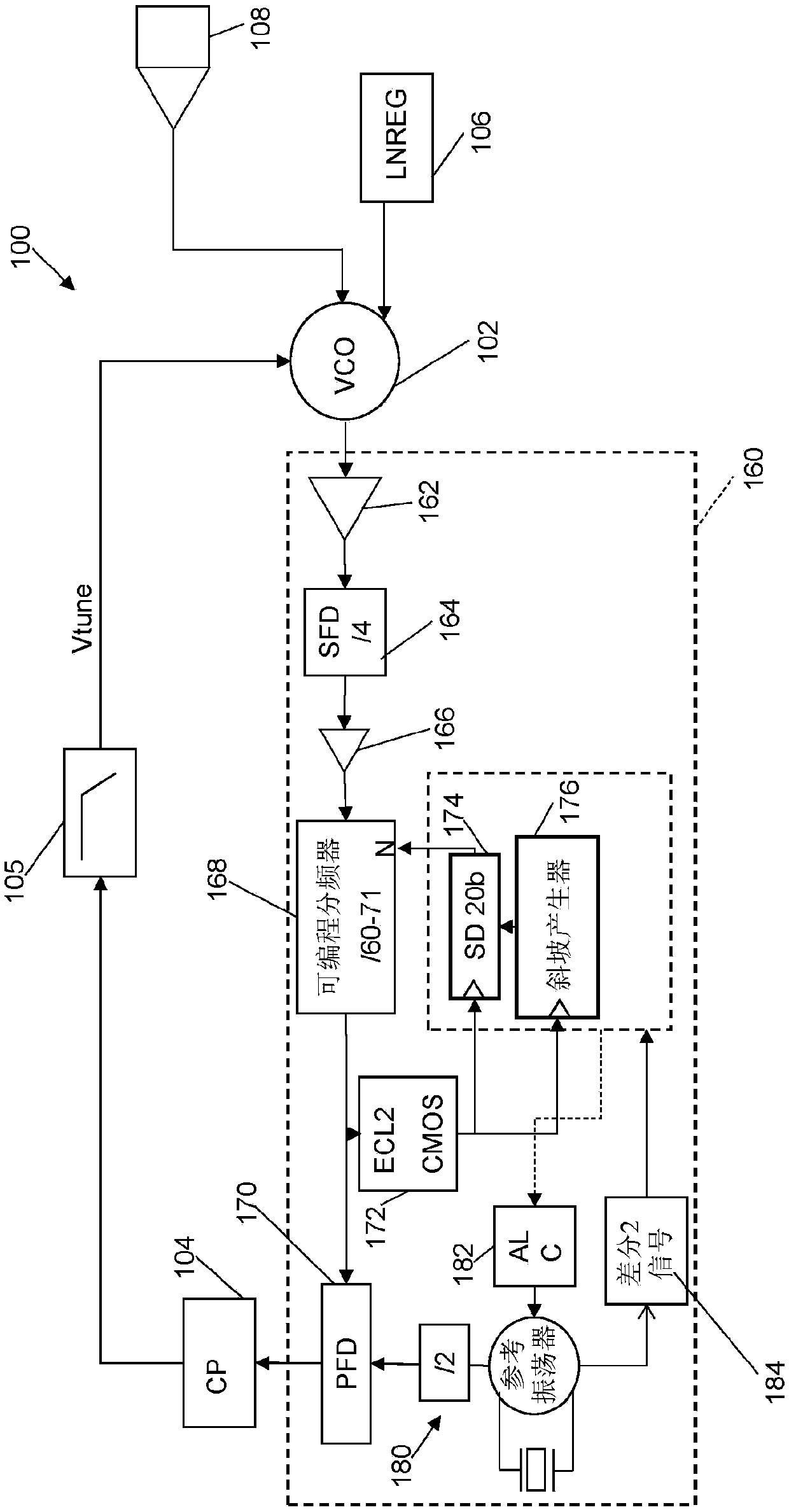
[0034] NXP's 'Eagle' dual-band (76-77GHz and 77-81GHz) automotive radar transceiver uses two voltage-controlled-oscillators in its main phase-locked loop (PLL) system, VCO) to achieve operation across two frequency bands. Two dedicated VCOs allow tuning range and phase noise requirements to meet the application range. The two VCOs are independently laser trimmed to cover the corresponding frequency bands. As described further below, see Figure 2b The implementation of the charge pump to provide the tuning voltage Vtune results in an operational constraint of the tuning voltage Vtune having a minimum operating voltage below which the charge pump (and PLL) may not operate properly. In some examples, the minimum operating voltage is about 0.6V. The minimum operating voltage constraint imposed on the tuning voltage during laser trimming has some disadvantages:

[0035] • It produces a productivity loss at the probe level;

[0036] · It limits the operating range of each resp...


PUM


Abstract

The invention relates to voltage-controlled-oscillator circuit comprising: a charge-pump configured to generate a tuning-voltage, the tuning-voltage having a minimum-operating-voltage; an offset-voltage-source configured to generate an offset-voltage in accordance with the minimum-operating-voltage; and a voltage-controlled-oscillator, VCO, configured to provide an oscillator frequency in accordance with the tuning-voltage and the offset-voltage.

Description

technical field [0001] The present disclosure relates to a voltage controlled oscillator circuit, and in particular, but not exclusively, to a voltage controlled oscillator circuit for a phase locked loop system in a radar transceiver. Background technique [0002] Radar transceivers are widely used in automotive applications, such as in impact detection and driver assistance systems. In some applications, it is desirable to provide radar transceivers that operate in multiple frequency bands. For example, a dual-band radar transceiver may operate at 76 to 77 GHZ and 77 to 81 GHZ. A dedicated voltage controlled oscillator (VCO) may be provided to implement each of the radar transceiver's operating frequency bands with a phase-locked loop (PLL) based frequency synthesizer. [0003] In some applications where it is desirable to be able to switch from one operating band to another in real time, it is difficult or not feasible to use two VCOs due to timing and frequency alignme...

Claims


Application Information

Patent Timeline
IPC IPC(8): H03L7/099H03L7/089H03L7/097
CPCH03L7/0895H03L2207/06H03L7/099H03L1/023G01S7/032
Inventor B·古巴拉P·P·萨瓦利C·帕瓦欧莫利拉
Owner NXP USA INC
Why Eureka
Try Eureka