A novel installation method of a camera under a screen
An installation method and camera technology, applied in image communication, color TV parts, TV system parts, etc., can solve the problems that the camera cannot take high-definition photos without light loss, and the lens protrudes
- Summary
- Abstract
- Description
- Claims
- Application Information
AI Technical Summary
Problems solved by technology
Method used
Image

Examples
specific Embodiment 1
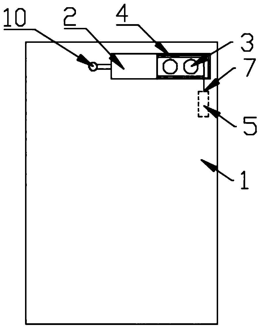
[0047] like figure 1 As shown, when the moving components are the rotor motor group 5 and the reset element 10, that is, when the driving force of the secondary screen 2 comes from the rotor motor group 5 and the reset element 10, one end of the secondary screen 2 is connected to the reset element 10, and the other end is passed through The ropes distributed on both sides of the camera group are connected to the rotating shaft of the rotor motor group 5; the main screen 1 is used for daily display. The screen 21 will be close to the main screen 1, and will completely block the camera assembly 3 located under the light transmission hole of the main screen 1, and when the mobile phone and computer need to use the camera located on the front of the screen, the electric motor located under the main screen 1 will Then, the secondary small screen 21 will be displaced to the side of the screen digging hole / notch area by positive rotation and pulling, so that the camera group can be e...
specific Embodiment 2
[0049]When the moving assembly is the rotor motor group 5 and the reset element 10, that is, when the driving force of the secondary screen 2 comes from the rotor motor group 5 and the reset element 10, when the positions of the motor group and the spring are changed, the installation method is the same as that of the specific embodiment 1, here The main screen 1 is used for daily display. When mobile phones and computers need to use a complete full screen, the display area of the secondary screen 2 can be pulled out by the rotation of the electric motor under the main screen 1. When mobile phones and computers need When using the camera, the display area of the secondary screen 2 can be reset through the reverse rotation of the electric motor and the pulling force of the reset element 10, and the camera can be presented in the light-transmitting hole of the main screen 1 through the gap part of the secondary screen 2 .
specific Embodiment 3
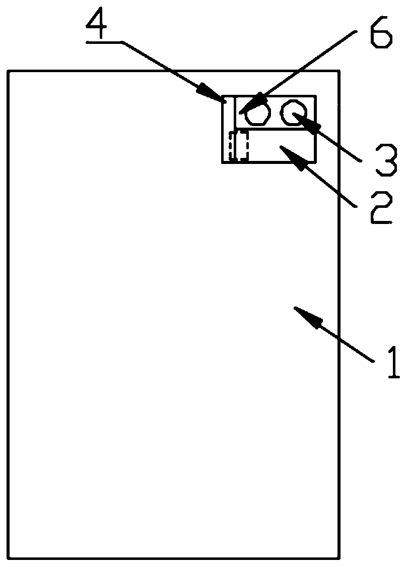
[0051] Such as figure 2 As shown, when the moving component is a linear motor 6, that is, when the driving force of the secondary screen 2 comes from a single linear motor 6, the secondary screen 2 is directly fixed and connected to the linear motor 6, and the main screen 1 is used for daily display. When mobile phones and computers need to use a complete full screen, the secondary small screen 21 located under the light transmission hole of the main screen 1 will be close to the main screen 1, and the camera assembly 3 located under the light transmission hole of the main screen 1 will be completely When the mobile phone or computer needs to use the camera located on the front of the screen, the linear motor 6 located under the main screen 1 will move the secondary screen 2 to the side of the light transmission hole of the screen through positive movement, so that The camera group can be exposed, and then, when the camera is no longer needed, the reverse movement of the elec...
PUM
 Abstract
Description
Claims
Application Information
 - R&D
- Intellectual Property
- Life Sciences
- Materials
- Tech Scout
- Unparalleled Data Quality
- Higher Quality Content
- 60% Fewer Hallucinations
Browse by: Latest US Patents, China's latest patents, Technical Efficacy Thesaurus, Application Domain, Technology Topic, Popular Technical Reports.
© 2025 PatSnap. All rights reserved.Legal|Privacy policy|Modern Slavery Act Transparency Statement|Sitemap|About US| Contact US: help@patsnap.com