Linear position sensing system and coil switching methods for closed-loop control of large linear induction motor systems

a linear induction motor and coil switching technology, applied in the field of linear induction motors, can solve the problems of system infeasibility, requiring so much electric power for exciting the entire stator, and not being able to achieve the effect of large switching number and avoiding potentially damaging lateral forces caused by switch failures

Active Publication Date: 2005-10-04
CURTISS WRIGHT ELECTRO MECHANICAL
View PDF35 Cites 70 Cited by
  • Summary
  • Abstract
  • Description
  • Claims
  • Application Information

AI Technical Summary

Benefits of technology

[0012]In accordance with at least one preferred embodiment, the present invention provides systems and methods for controlling linear induction motors. Specifically, the present invention includes control circuits for selectively switching stator coils, position sensing circuits for providing precise rotor positioning data, and failure prevention systems for negating the potentially adverse affects for coil switch failure.
[0015]Finally, the present invention also optionally includes adapted switch design for the stator coil section which “pairs” opposing coils in a dual-stator linear induction motor. By switching the stator coils in pairs in this way, and therefore reducing the number of switches by half, potentially damaging lateral forces called by switch failure can be avoided.

Problems solved by technology

However, this is typically not an effective approach for large linear induction motors because power transfer to the rotor or runner plate 120 only occurs over a small section of the stator 125 (adjacent to the instantaneous position of the runner 120).
In addition to the negative impacts on the motor, this approach also requires a larger sizing of the power inverter supplying the electrical energy to the motor.
For large accelerator applications such as aircraft or space payload launching (high acceleration of massive objects), exciting the entire stator may require so much electric power that the system becomes infeasible.

Method used


Image

  • Linear position sensing system and coil switching methods for closed-loop control of large linear induction motor systems
  • Linear position sensing system and coil switching methods for closed-loop control of large linear induction motor systems
  • Linear position sensing system and coil switching methods for closed-loop control of large linear induction motor systems

Examples


Embodiment Construction

[0028]The following detailed description includes various systems and methods for controlling a large linear induction motor to maximize its performance. In order to illustrate one potential application of the inventive aspects, an aircraft launching system is illustrated. However, the concepts described herein may be expanded to cover a wide variety of linear induction motors, especially when available power is limited and the linear induction motor is large. Each of the following concepts (i.e., stator switching, position sensing, and failure compensation) can be optionally used in combination or alone.

Stator Switching

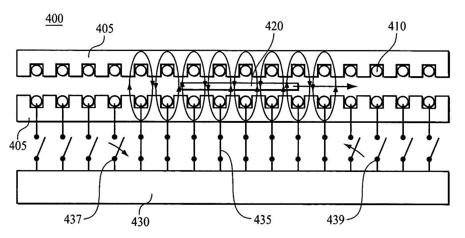
[0029]As a first linear motor control solution, the invention described herein deals specifically with a method of exciting the short secondary induction motor locally in the region where the reaction plate exists. In effect, the invention provides a method of producing a “window” of magnetic excitation that covers the runner plate at all times, but does not provide ...


PUM


Abstract

A control system for a linear motor adapted to accurately supply a moving window of power to the stator coils. A plurality of individually switched stator coils run the length of a linear motor to move a rotor down the long axis of the stator. Accurate inductive-based position sensors continuously provide position data for the moving rotor. A processing unit calculates a proper time delay from a source voltage peak in order to apply power to the next stator coil in the moving direction of the rotor such that no DC offshoot / undershoot occurs. The linear motor control system optionally includes a failure prevention switching scheme in which pairs of individual stator coils on opposite sides of a double-sided stator are switched together.

Description

BACKGROUND OF THE INVENTION[0001]1. Field of the Invention[0002]The present invention relates generally to linear induction motors, and, more specifically, the present invention relates to the control of large linear induction motor systems including inductive-based position sensing and stator coil switching algorithms.[0003]2. Description of the Background[0004]Linear induction motors are increasingly being designed for a wide variety of applications from moving loads to launching aircraft. For example, linear induction motors may be used for conveyor systems, material handling, transportation (people movers and trains), projectile accelerators and launchers, and machine tool operations. Large linear induction motors may even be used to launch aircraft from aircraft carriers, and very large “magnetic lifters” are being developed to launch payloads into space. Other applications of linear induction motors include: elevators for aircraft carriers and other locations; conveyors / packag...

Claims


Application Information

Patent Timeline
Patent Type & Authority Patents(United States)
IPC IPC(8): H02K41/00H02K17/30H02K41/025H02P25/06
CPCH02K17/30H02K41/025H02P25/06H02P25/062
Inventor KREFTA, MARK PETERHALL, DAVID JONATHANEICHLER, KENNETH MARTINWU, JIING-LIANGSTRICKLER, ROBERT E.BRENNEN, MICHAEL BARNABY
Owner CURTISS WRIGHT ELECTRO MECHANICAL
Why Eureka
Try Eureka