Rail carriage and rail carriage system

a rail carriage and carriage technology, applied in the direction of program-controlled manipulators, loading/unloading, storage devices, etc., can solve the problems of labor-intensive tasks, expensive and time-consuming, and achieve the effect of simple end-to-end manufacturing

Inactive Publication Date: 2006-03-02
MAYNARD MICHAEL D +2
View PDF29 Cites 73 Cited by
  • Summary
  • Abstract
  • Description
  • Claims
  • Application Information

AI Technical Summary

Benefits of technology

[0008] An object is to provide a carriage for the intended purpose which is simple end easily manufactured.

Problems solved by technology

The task is labor intensive, expensive and time consuming.

Method used


Image

  • Rail carriage and rail carriage system
  • Rail carriage and rail carriage system
  • Rail carriage and rail carriage system

Examples


Embodiment Construction

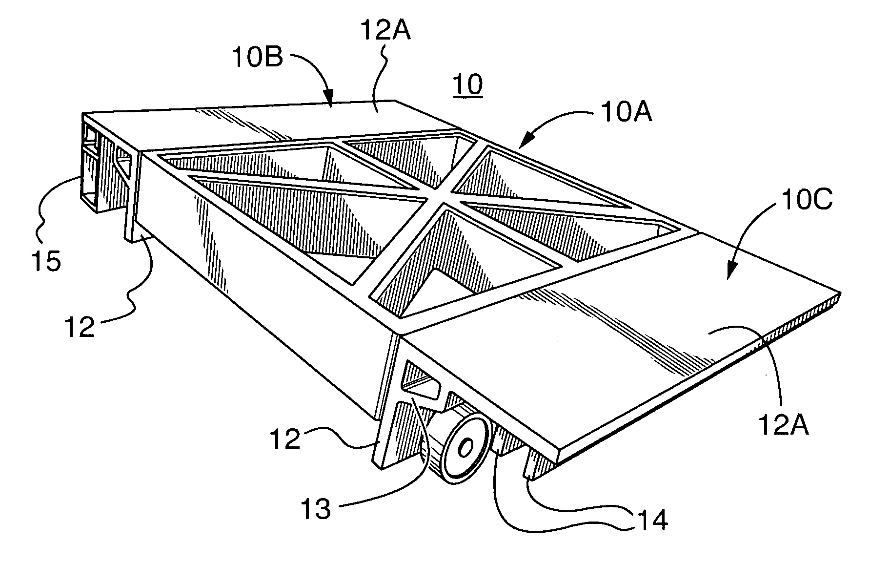
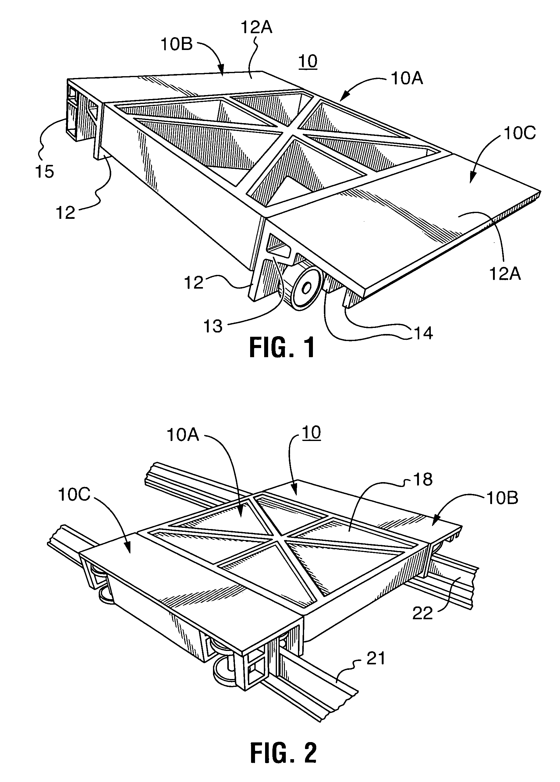
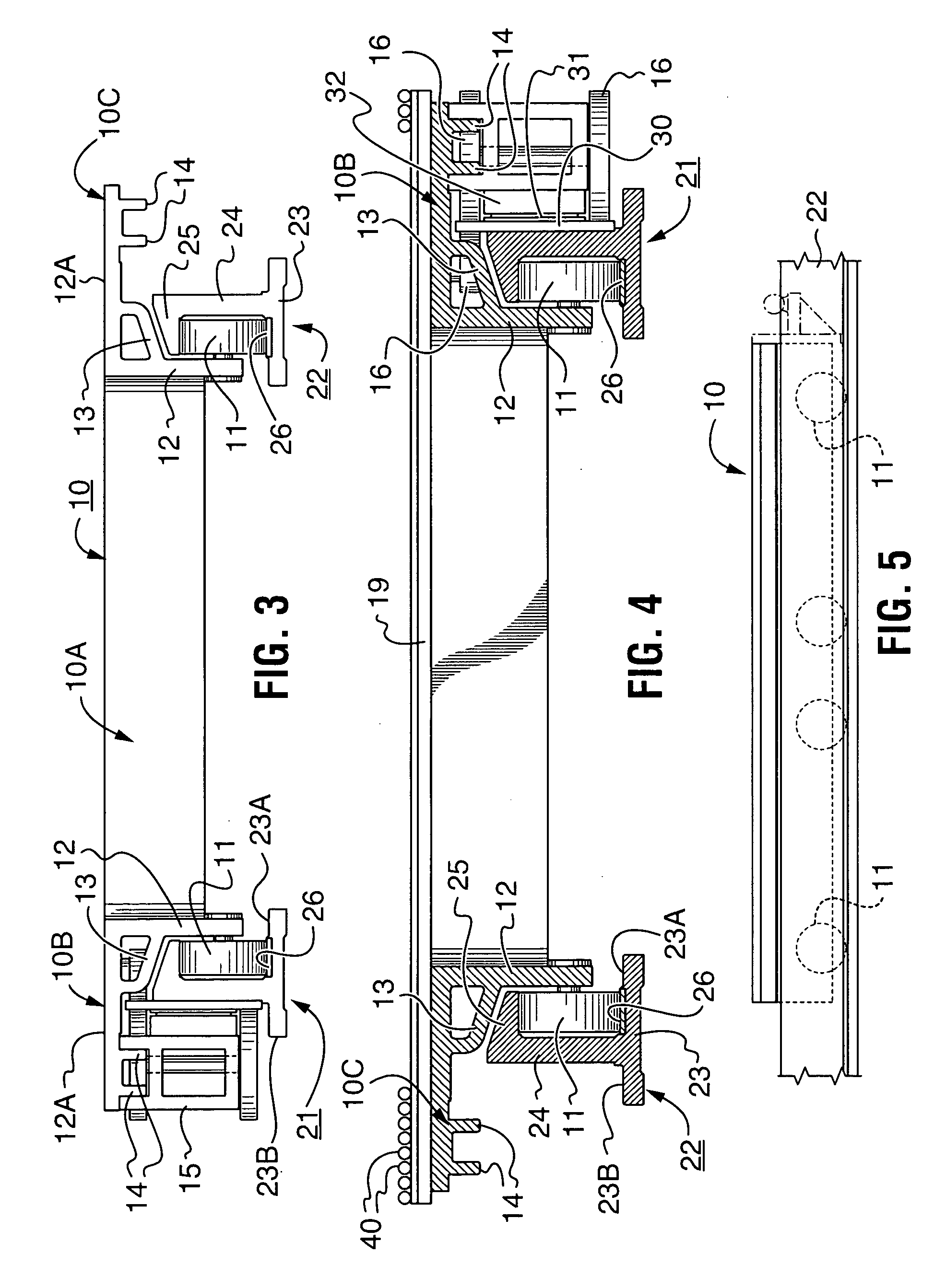
[0069] Illustrated in FIGS. 2 and 3 is a rail carriage 10 rolling mounted on a rail system 20 comprising a spaced apart pair of rails 21, 22.

[0070] The rails 21, 22 of one preferred embodiment are aluminum extrusions that have a bottom flange 23, an upwardly projecting web 24 and a top laterally directed flange 25. Of course the rails can be composed of any nonmagnetic material having sufficient structural strength and rigidity. The flanges 23, 25 and the web therebetween define a channel receiving therein a first plurality of rollers 11 journalled on the carriage. Flange 23 has portions 23A, 23B respectively on opposite sides of the web and these rollers run on a strip 26 of wear resistant material, for example steel, secured to the rail flange portion 23A.

[0071] The carriage 10 comprises a central load support member 10A and elongate members 10B, 10C detachably secured thereto along respective opposite parallel sides thereof.

[0072] The central support member has an outer periph...


PUM


Abstract

A track and carriage system that includes a pair of spaced apart parallel rails and a carriage rollingly mounted on the rails. The carriage is a rectangular, in plan view, structural unit having a pair of opposite parallel marginal edges with a frame side rail secured to each of the marginal edges. Rollers journalled on the side rails rollingly support the carriage on the rails. A motor mounting subassembly carried by the carriage provides a downwardly facing channel that receives therein a portion of one of the rails. A plurality of rollers on the motor mounting subassembly maintains a minium air gap between a linear motor mounted on the subassembly and a magnetic strip on an adjacently disposed side face of one of the rails. The carriage structural portion maybe a plurality of beams disposed side-by-side or one or more extruded monolithic cast structures. A structural plate like member maybe mounted on the load carrying frame. If desired a power driven roller conveyor maybe mounted on the carriage for loading and off loading goods. Also the motor mounting subassembly and a frame side rail secured thereto running on a single rail provides a mono rail transfer vehicle.

Description

RELATED APPLICATIONS [0001] This application and claims priority from Provisional application Ser. No. 60 / 558,356 filed on Mar. 31, 2004 and is a Continuation-In-Part of Ser. No. 10 / 895,031 filed on Jul. 20, 2004, which is a Continuation-In-Part of U.S. Pat. No. 6,764,266 which issued on Jul. 20, 2004 from application Ser. No. 09 / 902,477 filed on Jul. 10, 2001, which is a Continuation-In-Part of U.S. Pat. No. 6,257,821 which issued on Jul. 10, 2001 from application Ser. No. 09 / 363,622 filed on Jul. 29, 1999, which is a Continuation-In-Part of U.S. Pat. No. 6,234,737 which issued on May 22, 2001 from application Ser. No. 08 / 898,073 filed on Jul. 22, 1997, all of which are hereby incorporated by reference.TECHNICAL FIELD OF THE INVENTION [0002] This invention relates generally to remotely controllable article handling system and more particularly to a carriage and track system and rail carriages for use on a track or track system wherein the carriage is propelled along the track by a ...

Claims


Application Information

Patent Timeline
Patent Type & Authority Applications(United States)
IPC IPC(8): B65G1/00B25J5/02B25J9/02B65G1/04
CPCB25J5/02B65G1/0435B65G1/0407B25J9/026
Inventor MAYNARD, MICHAEL D.YOUNG, RICHARD C.WARD, RONALD E.
Owner MAYNARD MICHAEL D
Why Eureka
Try Eureka