
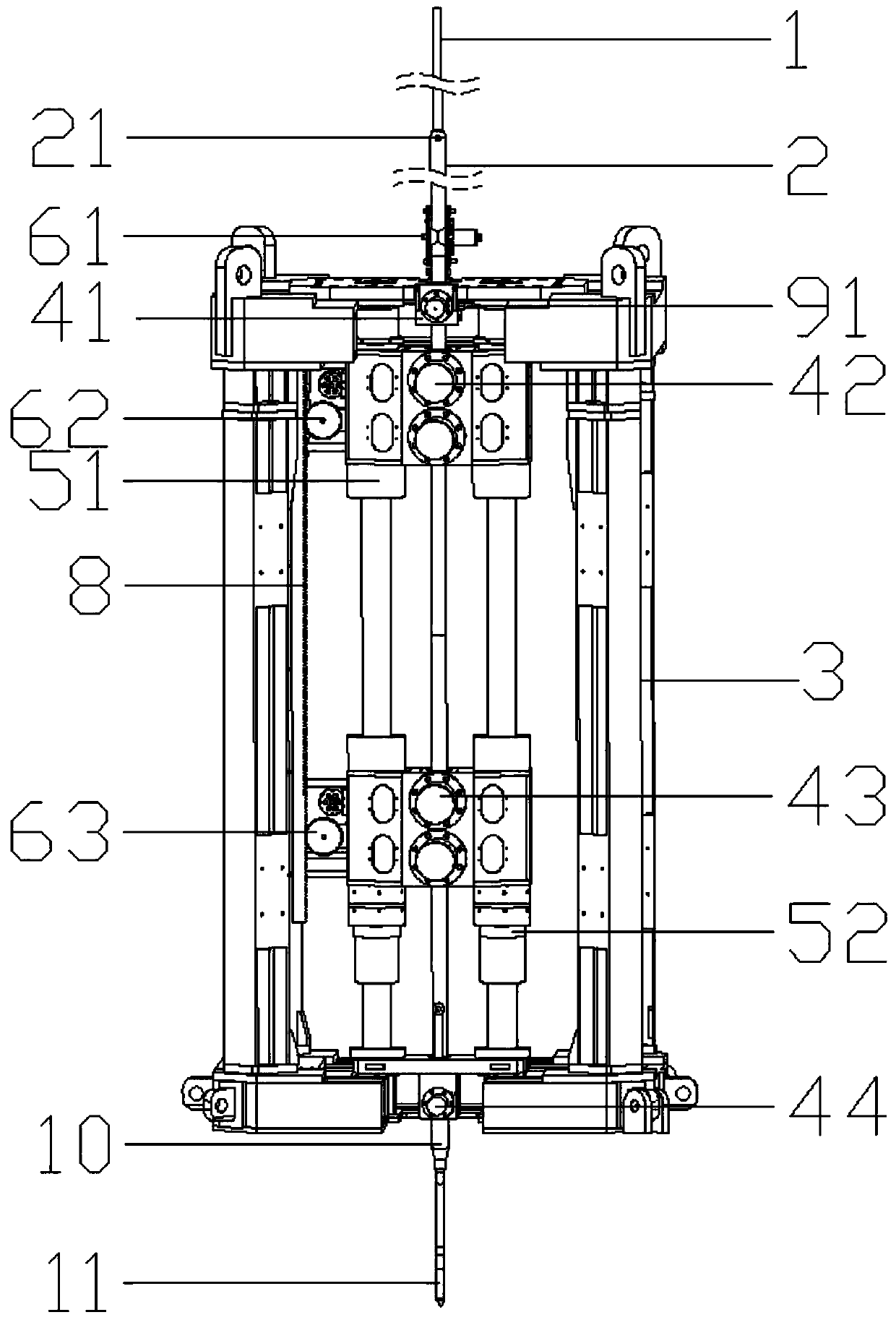
Cone penetration test device with casing function and continuous penetration construction technology

A technology of static penetration and casing, which is applied in foundation structure engineering, on-site foundation soil survey, construction, etc. It can solve problems such as shallow penetration depth, failure to detect casing penetration in place, and failure to penetrate casing. , to achieve the effect of increasing the penetration depth, preventing self-locking failure accidents, and improving the penetration force and pull-out force

Pending Publication Date: 2019-06-25
武汉吉欧信海洋科技股份有限公司
View PDF0 Cites 4 Cited by
  • Summary
  • Abstract
  • Description
  • Claims
  • Application Information

AI Technical Summary

Problems solved by technology

[0003] The traditional mechanical and hydraulic static penetrating machines, because of the intermittent feed mode of the single oil cylinder group, usually have an obvious acceleration process at the beginning of one probe rod, and at the same time between the two probe rods There is a period of pause between them, which is used for the return of the feeding mechanism and the addition of the probe rod, so that the speed of the probe rod penetrating into the soil layer is not uniform, continuous and stable. At the beginning and end of each probe rod due to the penetration The speed does not meet the specification requirements, resulting in bad test data, which affects the acquisition of complete soil layer data
[0004] There are also some double oil cylinder groups that can perform continuous penetration, but they are not perfect enough to allow casing penetration, only probe rod penetration, the penetration depth is shallow, and there is no function of detecting whether the casing is penetrated in place

Method used


Image

  • Cone penetration test device with casing function and continuous penetration construction technology
  • Cone penetration test device with casing function and continuous penetration construction technology
  • Cone penetration test device with casing function and continuous penetration construction technology

Examples


Embodiment Construction

[0040] The technical solutions of the present invention will be clearly and completely described below in conjunction with the accompanying drawings of the present invention. Based on the embodiments of the present invention, all other embodiments obtained by persons of ordinary skill in the art without creative efforts fall within the protection scope of the present invention.

[0041] In the description of the present invention, it should be noted that the terms "upper", "lower", "inner", "outer", "front end", "rear end", "both ends", "one end", "another end" The orientation or positional relationship indicated by etc. is based on the orientation or positional relationship shown in the drawings, and is only for the convenience of describing the present invention and simplifying the description, rather than indicating or implying that the referred device or element must have a specific orientation, use a specific Azimuth configuration and operation, therefore, should not be c...


PUM


Abstract

The invention discloses a cone penetration test device with a casing function and a continuous penetration construction technology. The cone penetration test device comprises a feeler lever, a casing,a rack, a first transverse clamping mechanism, a second transverse clamping mechanism, a third transverse clamping mechanism, a fourth transverse clamping mechanism, a longitudinal continuous penetration mechanism, a depthometer, a proximity switch and a controller, the lower end of the casing is connected with the feeler lever through a self-locking mechanism, and the longitudinal continuous penetration mechanism is divided into upper and lower groups of penetration mechanisms. The continuous penetration construction technology is characterized in that alternate circular downward movement ofthe two groups of penetration mechanisms is utilized by the device; the casing and the feller lever are driven by the transverse clamping mechanisms to penetrate downward simultaneously; when the casing is penetrated in place is calculated by cooperatively using the proximity switch and the depthometer; when the casing is penetrated in place, alternate penetration on the feeler lever is carried out by the penetration mechanism individually; after a cone penetration test is completed, pulling is carried out on the feller lever by the longitudinal continuous penetration mechanism firstly; and after the proximity switch detects that the feller lever is self-locked in place, alternate pulling on the casing and the feeler lever is carried out simultaneously.

Description

technical field [0001] The invention relates to the technical field of static penetration testing, in particular to a static penetration testing device with casing function and a continuous penetration construction process. Background technique [0002] As a method of in-situ testing of soil in the field of geotechnical engineering technology, static penetration testing is to use the feeding device to penetrate the probe rod with the probe at the bottom into the soil layer, and evaluate parameters such as penetration resistance and friction. The basic physical and mechanical properties of the soil, such as the deformation modulus of the soil, the allowable bearing capacity of the soil, etc. According to the technical specifications of static penetrating sounding, it is required that the probe rod should maintain a continuous and stable feed at a constant speed in the process of penetrating into the soil layer, so that continuous and stable soil layer test data can be obtaine...

Claims


Application Information

Patent Timeline
IPC IPC(8): E02D1/02
CPCY02E30/30
Inventor 张黄瑞鑫王盼干金柳
Owner 武汉吉欧信海洋科技股份有限公司
Learn More