
A Continuously Penetrating Mechanical Cross Plate Shear Meter with Clutch Gears

A cross-plate, mechanical technology, applied in the field of mechanical cross-plate shear force meter, can solve the problems of no tube shoe protection, continuous penetration, etc., to achieve the effect of ensuring accuracy

Active Publication Date: 2021-01-12
TIANJIN PORT ENG INST LTD OF CCCC FIRST HARBOR ENG +2
View PDF8 Cites 0 Cited by
  • Summary
  • Abstract
  • Description
  • Claims
  • Application Information

AI Technical Summary

Problems solved by technology

[0004] The existing clutch-type mechanical cross-plate shear instrument can correct the frictional resistance between the inner rod and the casing, but because the head of the cross-plate is exposed outside the pipe shoe, there is no protection of the pipe shoe, so continuous penetration cannot be performed.

Method used


Image

  • A Continuously Penetrating Mechanical Cross Plate Shear Meter with Clutch Gears
  • A Continuously Penetrating Mechanical Cross Plate Shear Meter with Clutch Gears
  • A Continuously Penetrating Mechanical Cross Plate Shear Meter with Clutch Gears

Examples


Embodiment 1

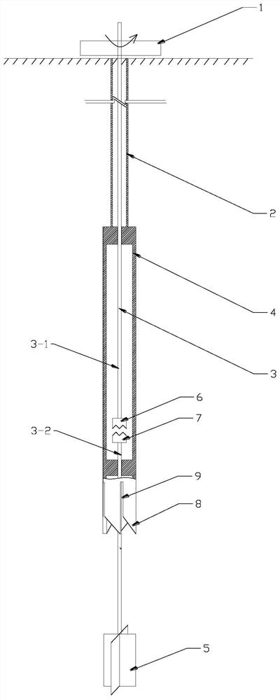
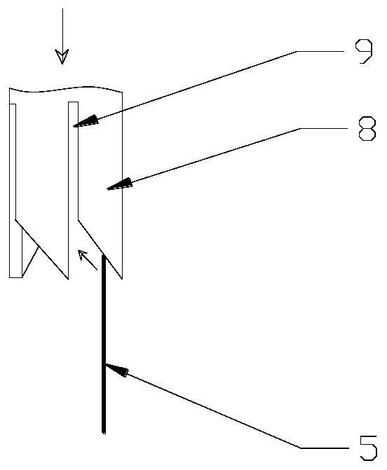
[0040] See attached Figure 1-4 , a mechanical cross-plate shearing instrument with clutch teeth that can be continuously penetrated, including a torque steel ring 1, an outer tube 2, an inner rod 3, a tube shoe 4, and a cross plate 5.

[0041] The bottom end of the outer tube 2 is connected to the boot 4, the inner rod 3 is coaxially arranged in the outer tube 2 and the boot 4, the torque steel ring 1 is set on the top of the inner bar 3, and the upper and lower groups are arranged in the boot 4 Clutch teeth 6 and 7, the inner rod includes an upper rod segment 3-1 and a lower rod segment 3-2, the upper rod segment and the lower rod segment are split, and the bottom end of the upper rod segment 3-1 is fixedly connected to the upper clutch tooth 6 , the top of the lower rod section 3-2 is fixedly connected to the lower clutch tooth 7, and through the cooperation of the upper and lower clutch teeth, the connection and separation between the upper rod section and the lower rod se...

Embodiment 2

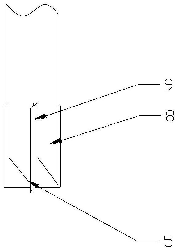
[0058] See attached Figure 5 with 6 The difference between this embodiment and Embodiment 1 is that the wall thickness of the inclined guiding boss 8 is relatively large, and the outer diameter of the cross plate 5 is smaller than the outer diameter of the circular area surrounded by the inclined guiding boss 8 , that is, after the cross plate enters the elongated hole between the guiding inclined bosses, the outer edge of the cross plate 5 is within the outer wall of the guiding inclined boss 8, so that the cross plate can completely enter the tube shoe, thereby more effectively protecting the cross plate plate.


PUM

PropertyMeasurementUnit
Thicknessaaaaaaaaaa

Abstract

The invention discloses a continual-injection mechanical vane-shear apparatus with clutch gears, comprising a torque steel ring, an outer pipe, an inner rod, a pipe shoe, and a cross vane, wherein thebottom of the outer pipe is connected with the pipe shoe, an upper clutch gear and a lower clutch gear are arranged in the pipe shoe, the inner rod is composed of an upper rod section and a lower rodsection, both the upper rod section and lower rod section are in a split type, the bottom of the upper rod section is fixedly connected with the upper clutch gear, the top of the lower rod section isfixedly connected with the lower clutch gear, and the upper clutch gear and the lower clutch gear work together to realize connection and separation of the upper rod section and the lower rod section; the cross vane is fixedly arranged at the bottom of the lower rod section; four guided inclined bosses are arranged in the periphery along an opening at the bottom of the pipe shoe and stripped holes for accommodating blades of the cross vane are arranged between adjacent guided inclined bosses. Under a guided effect of the guided inclined bosses in pressing process, the cross vane can be exactly put in the stripped holes along inclined faces of the guided inclined bosses to protect the cross vane to implement a continual injection.

Description

technical field [0001] The invention belongs to the improvement of a cross-plate shear instrument in the field of geotechnical engineering investigation, in particular to a mechanical cross-plate shear instrument with clutch teeth that can penetrate continuously. Background technique [0002] In geotechnical engineering investigation, in order to determine the soil layer distribution and related physical and mechanical parameters of the foundation, it is usually necessary to take undisturbed soil samples for indoor tests, but because the soil samples will be disturbed during the process of taking soil samples, the in-situ test results are obtained. wider application. In soft soil areas, where the soil has high water content and low shear strength, the cross-plate shear test can accurately measure the shear strength of the soil, so it has unique advantages in the fields of foundation bearing capacity and stability calculation. [0003] Existing cross-plate shear instruments ...

Claims


Application Information

Patent Timeline
IPC IPC(8): G01N3/24
CPCG01N3/24G01N2203/0037
Inventor 陈富张健李彪李立新侯晋芳
Owner TIANJIN PORT ENG INST LTD OF CCCC FIRST HARBOR ENG
Learn More