Pneumatic type architectural design drawing board frame

A kind of architectural design and pneumatic technology, which is applied in the direction of drawing desks, tables, household appliances, etc., can solve the problems of fast fixed height adjustment and inclination adjustment, so as to avoid blockage of drawing content, high usability and strong adaptability Effect

Inactive Publication Date: 2019-06-28
牧弢
View PDF1 Cites 5 Cited by
  • Summary
  • Abstract
  • Description
  • Claims
  • Application Information

AI Technical Summary

Problems solved by technology

Chinese patent (notification number CN208192572U) discloses a drawing frame for architectural design. Although the problem has been solved to a certain extent, there are still problems in fast fixing, unobstructed fixing, height adjustment and inclination adjustment.

Method used


Image

  • Pneumatic type architectural design drawing board frame
  • Pneumatic type architectural design drawing board frame
  • Pneumatic type architectural design drawing board frame

Examples


Embodiment 1

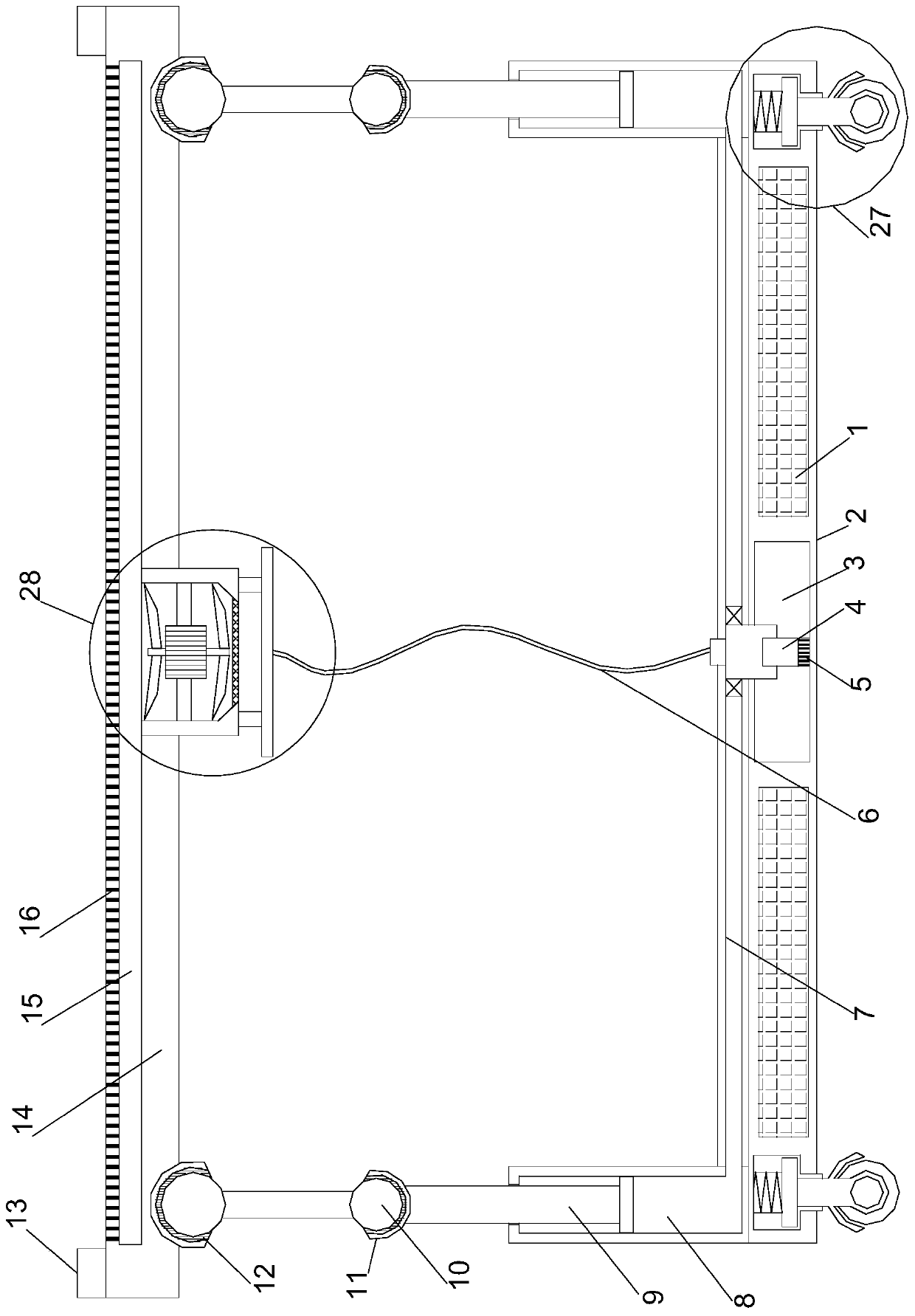
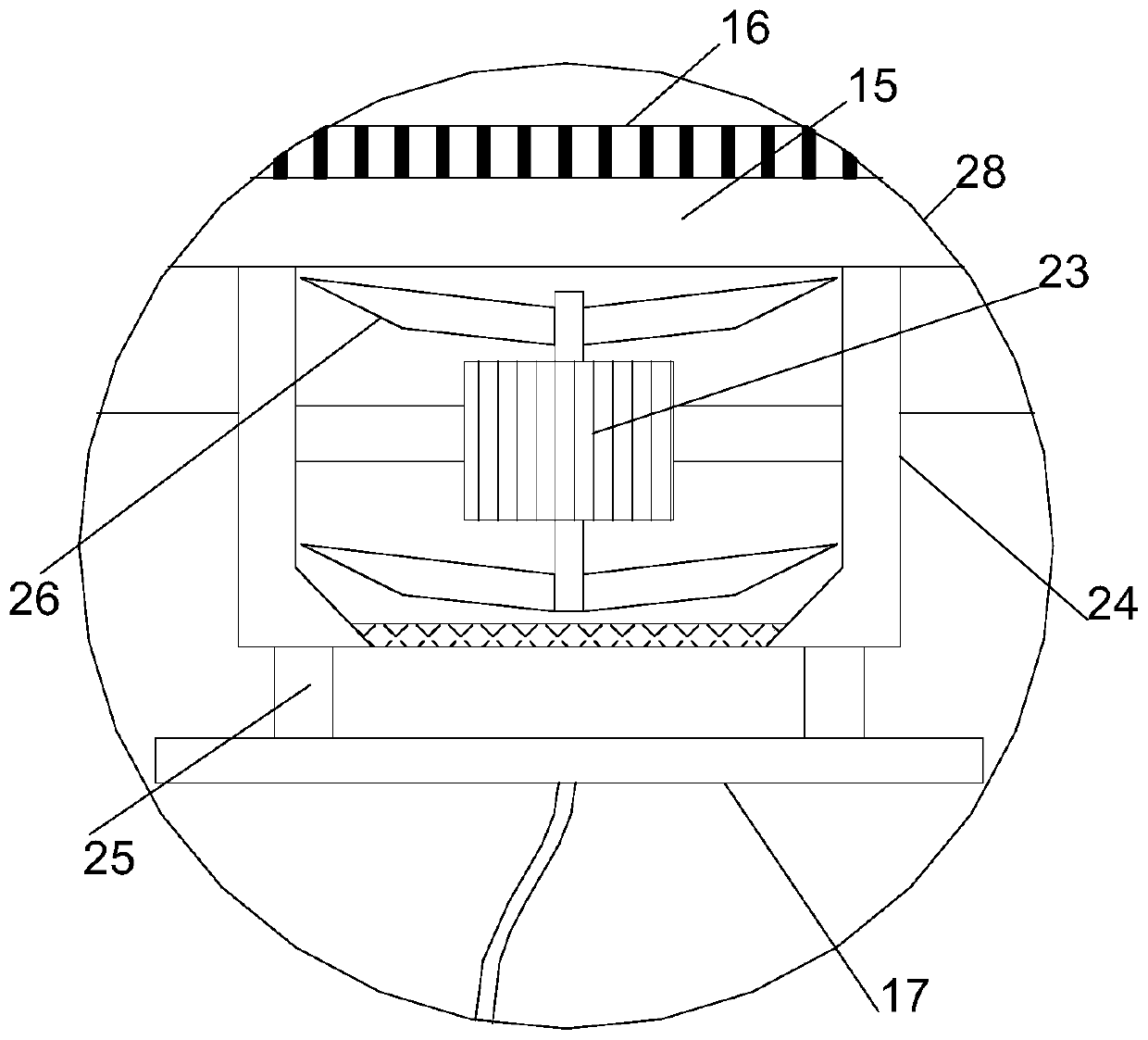
[0024] see Figure 1~4 , in an embodiment of the present invention, a pneumatic architectural design drawing board frame includes a support mounting plate 2 arranged horizontally, a drawing board 14 is horizontally arranged directly above the support mounting plate 2, and the four corners of the upper end of the support mounting plate 2 are The limit lifting hydraulic cylinder 8 is vertically arranged, and the upper end of the limit lifting hydraulic cylinder 8 is connected with the drawing board 14 through a positioning swing structure. All are provided with a shock-absorbing steering moving structure 27, and the drawing board 14 is provided with a drawing pneumatic fixing structure 28, and the hydraulic driving structure includes a hydraulic oil tank 3 that is horizontally inlaid in the middle of the support installation plate 2, and the middle of the upper end of the hydraulic oil tank 3 The position is vertically provided with an oil delivery pipe, and the upper end of the...

Embodiment 2

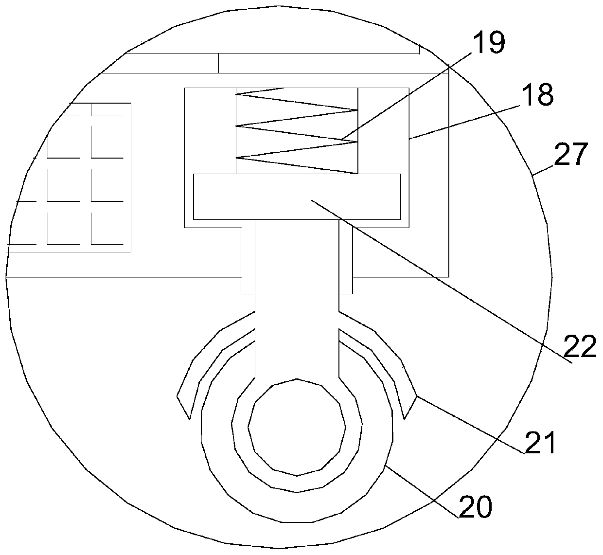
[0028] On the basis of Embodiment 1, the shock-absorbing and steering moving structure 27 includes vertical guide grooves 18 inlaid vertically at the four corners of the support mounting plate 2, and the inside of the vertical guide grooves 18 is horizontally provided with a limit steering plate 22, so that The middle position of the position-limiting steering plate 22 is installed with a rotating wheel frame 21 vertically and coaxially downward, and the lower end of the rotating wheel frame 21 is provided with a moving guide wheel 20 through a rotating shaft. Straight guide groove 18 is vertically installed with vertical shock absorbing spring 19, cooperates with rotating wheel frame 21 by limit steering plate 22, realizes turning, realizes efficient movement by moving guide wheel 20, and it is damped by vertical shock spring 19. Under the action of earthquake, the stable transfer of the device is realized, and the mobility is strong.


PUM


Abstract

The invention relates to the field of design of architectural design and specifically relates to a pneumatic type architectural design drawing board frame. The pneumatic type architectural design drawing board frame comprises a horizontally arranged support mounting plate, a drawing board is horizontally arranged right above the support mounting plate, limiting lifting hydraulic cylinders are vertically arranged on four corners at the upper end of the support mounting plate, the upper end of the limiting lifting hydraulic cylinder is connected with the drawing board through a locating swingingstructure, a hydraulic drive structure is arranged at the inner part of the support mounting plate, shock absorption steering moving structures are arranged on four corners at the lower end of the support mounting plate, a drawing board pneumatic fixing structure is arranged on the drawing board, an air cushion of the drawing board is adsorbed and fixed through even diversion, so that the drawingboard can be placed and used, the characteristic of rapid and stable fixing is achieved, the condition that the content of the drawing board is blocked because of the traditional magnetic adsorptionis avoided, the device is quite easy to use, the synchronous lifting height regulation and the differential lifting inclination regulation are implemented through hydraulic drive, so that the adaptability of the device is quite strong.

Description

technical field [0001] The invention relates to the field of architectural construction design, in particular to a pneumatic architectural design drawing frame. Background technique [0002] Architectural design drawings refer to the display of the designer on the drawings and documents according to the construction tasks before the building is constructed. The demand has also increased. Take the drawing board rack for design as an example, which is mainly used for drawing design. There are many types and styles of design board racks on the market. Chinese patent (notification number CN208192572U) discloses a drawing board frame for architectural design. Although the problem has been solved to a certain extent, there are still problems in fast fixing, unobstructed fixing, height adjustment and inclination adjustment. [0003] The present invention aims to solve the technical problems existing in the prior art. To this end, a pneumatic architectural design drawing frame is p...

Claims


Application Information

Patent Timeline
Patent Type & Authority Applications(China)
IPC IPC(8): A47B27/02A47B27/16
Inventor 牧弢张荣芳吕珊琳
Owner 牧弢
Why Eureka
Try Eureka