Corrosive foil cleaning device

A cleaning device and a technology for corroding foil, which is applied in the field of corroding foil processing, can solve the problems of no brushing structure, insufficient cleaning effect, long cleaning time, etc., and achieve the effect of ensuring and improving the cleaning effect

Inactive Publication Date: 2019-06-28
JIANGSU LIFU ELECTRODE FOIL
View PDF1 Cites 3 Cited by
  • Summary
  • Abstract
  • Description
  • Claims
  • Application Information

AI Technical Summary

Benefits of technology

This patented device has several technical benefits compared to previous devices. Firstly it uses an improved method for removing rust from metal parts during maintenance operations without causing damage or requiring expensive repairs. Secondly, this technology improves upon existing methods while still maintain its efficiency at killing unwanted substances like chlorides. Thirdly, these techniques help prevent contamination caused by residual chemicals left behind after repair work.

Problems solved by technology

This technical problem addressed by this patented technology relates to producing high purity metallic materials that can maintain their quality during storage or transportation without losing any residue from contamination caused by environmental factors such as moisture and oxygen. Traditional methods involve adding detergents before washing, but these techniques have limitations due to excessive amounts of liquid needed per unit area. Therefore, an improved solution needs to be developed to improve upon existing technologies like chemical etchants and mechanical polishing processes.

Method used


Image

  • Corrosive foil cleaning device
  • Corrosive foil cleaning device
  • Corrosive foil cleaning device

Examples


Embodiment 1

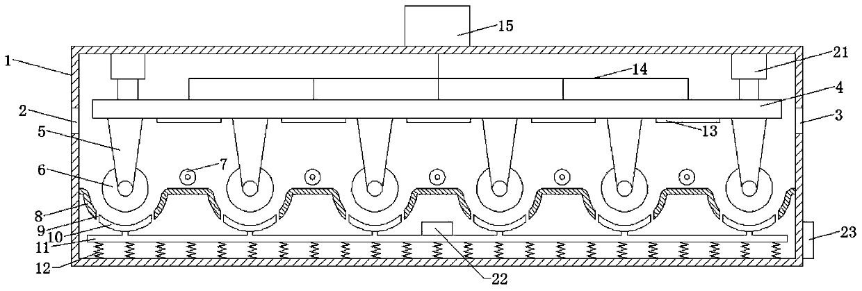
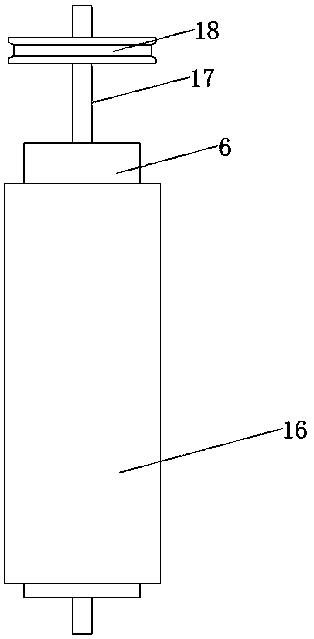
[0019] Please refer to the figure. In the embodiment of the present invention, a corrosion foil cleaning device includes a casing 1, a feed port 2, a discharge port 3, a lifting plate 4 and a circulating pump 15; the feed port 2 is opened in the casing On the left side wall of 1, the discharge port 3 is opened on the right side wall of the housing 1. The feed port 2 and the discharge port 3 are on the same horizontal plane, so that the corroded foil enters from the feed port 2. The corrosion after cleaning The foil is sent out from the discharge port 3; the lifting plate 4 is horizontally arranged in the housing 1, and the two ends of the lifting plate 4 are fixedly connected with a lifting device 21 that is telescopic in the vertical direction, and the height of the lifting plate 4 is adjusted by the lifting device 21 A plurality of brackets 5 are equidistantly arranged on the lower surface of the lifting plate 4, and a horizontal shaft 17 is rotatably connected to the bracket ...

Embodiment 2

[0023] The lower sides of the plurality of brush plates 10 are fixedly connected by a support rod 11, the lower side of the support rod 11 is fixedly connected with a plurality of springs 12, the lower ends of the springs 12 are fixedly connected to the bottom of the housing 1, and the brush plates 10 are supported by the springs 12 A vibration motor 22 is installed on the brush plate 10, and the vibration motor 22 drives the entire brush plate 10 to shake, thereby improving the cleaning effect of the corroded foil.

[0024] When in use, the corrosion foil enters from the feed port 2, alternately bypassing the internal driving roller 6 and guide roller 7, the driving roller 6 drives the corrosion foil to convey to the right, the driving roller 6 extends into the cleaning tank 8 and the internal deionization The upper surface of the corroded foil is in contact with the brush cover 16 on the surface of the driving roller 6, the upper surface is sprayed with deionized water through t...


PUM


Abstract

The invention relates to the field of corrosive foil machining and particularly discloses a corrosive foil cleaning device. The corrosive foil cleaning device comprises a shell, a feeding port, a discharging port, a lifting plate and a circulating pump; the lower surface of the lifting plate is provided with a plurality of supports at equal intervals; horizontal rotating shafts are rotationally connected to the supports through bearings; the outer sides of driving rollers are each fixedly sleeved with a layer of brush sleeve; a plurality of sprinkling pipes are fixedly installed on the lower surface of the lifting plate; an arc-shaped cleaning groove is arranged below each driving roller; center shafts of the cleaning grooves coined with the rotating shafts; the shell is internally filledwith cleaning liquid; the bottom of each cleaning groove is provided with an opening; and a brush plate the same as the corresponding cleaning groove in radian is arranged in each opening. According to the corrosive foil cleaning device, the upper surface of corrosive foil is contact with the brush sleeves on the surfaces of the driving rollers, deionized water is jetted onto the upper surface through the sprinkling pipes so that the upper surface of the corrosive foil can be washed, the lower surface is in contact with bristle layers on lower brush plates, impurities of the surface of the corrosive foil is brushed away due to vibration of the brush plates, and cleaning treatment is performed on the upper surface and the lower surface of the corrosive foil at the same time.

Description


Claims


Application Information

Patent Timeline
Owner JIANGSU LIFU ELECTRODE FOIL
Why Eureka
Try Eureka