Target object conveying method and device

A target object, target technology, applied in the field of target object transmission method and device, can solve the problem of low transmission efficiency

Active Publication Date: 2019-06-28
WEIHAI NEWBEIYANG ZHENGQI ROBOT
View PDF6 Cites 6 Cited by
  • Summary
  • Abstract
  • Description
  • Claims
  • Application Information

AI Technical Summary

Problems solved by technology

[0003] In view of this, the object of the present invention is to provide a target object transmission method and device to alleviate the technical problem of low transmission efficiency of the existing target object transmission method

Method used


Image

  • Target object conveying method and device
  • Target object conveying method and device
  • Target object conveying method and device

Examples


Embodiment 1

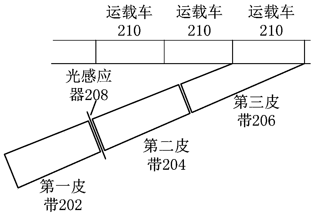
[0030] This embodiment provides a target object transfer method, refer to figure 1A flow chart of a target object transmission method is shown. The method is applied to the controller, and the controller is connected with the transmission mechanism. The transmission mechanism includes sequentially connecting the first belt, the second belt and the third belt. For ease of understanding, figure 2 A schematic diagram of a belt layout of a transmission mechanism is shown, including a first belt 202 , a second belt 204 and a third belt 206 . The above-mentioned connection of the first belt, the second belt and the third belt refers to a connection method arranged sequentially in the conveying direction, not a physical or mechanical connection.

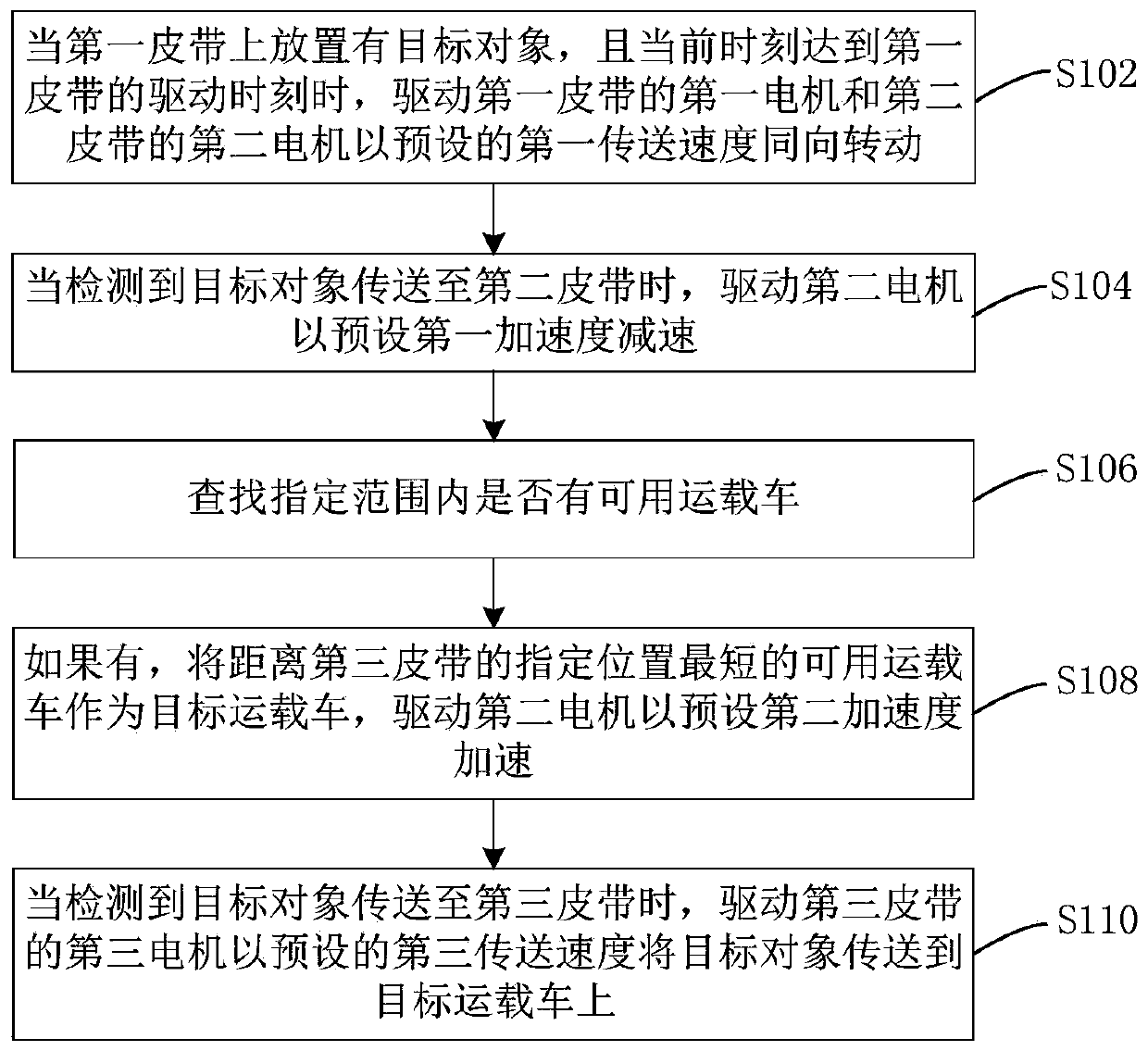
[0031] The method includes the following steps:

[0032] Step S102, when the target object is placed on the first belt, and the current time reaches the driving time of the first belt, the first motor driving the first belt and the secon...

Embodiment 2

[0083] This embodiment also provides a target object transmission device, refer to Figure 4 A structural schematic diagram of a target object transmission device is shown, the device is applied to the controller, the controller is connected to the transmission mechanism, and the transmission mechanism includes sequentially connecting the first belt, the second belt and the third belt, and the device includes:

[0084] The transmission driving module 402 is configured to drive the first motor of the first belt and the second motor of the second belt at a preset first speed when the target object is placed on the first belt and the current time reaches the driving time of the first belt. - Rotate in the same direction at the transmission speed;

[0085] A deceleration drive module 404, configured to drive the second motor to decelerate with a preset first acceleration when it is detected that the target object is transmitted to the second belt;

[0086] A search module 406, co...


PUM


Abstract

The invention provides a target object conveying method and device, and relates to the technical field of conveying. According to the method, a first motor of a first belt and a second motor of a second motor are driven to move in the same direction after a target object is placed on the first belt, the second motor is driven to uniformly decelerate when it is detected that the target object is conveyed to the second belt; when it is detected that there exists an available carrier in a designated range, the available carrier with the shortest distance from the designated position of a third belt is taken as a target carrier, and the second motor is driven to uniformly accelerate; when it is detected that the target object is conveyed to the third belt, a third motor on the third belt is driven to convey the target object to the target carrier. The method and the device have the advantages that it is ensured that the target object is not rotated in the conveying process by the manner inwhich the rotation rates of the first motor and the second motor are the same, and the conveying efficiency of the target object is improved by the manner in which the target object is decelerated towait for the target carrier and accelerated to be conveyed after the target carrier is positioned.

Description

technical field [0001] The present invention relates to the technical field of transportation, in particular to a method and device for conveying a target object. Background technique [0002] At present, in order to improve the transmission efficiency of the luggage (target object) transported by the passenger transport mechanism and improve the buffer capacity of the transport, most of the existing passenger transport mechanisms are equipped with multiple motors, and each motor is equipped with a rotating belt. Among them, since the rotational speed of each motor is different in advance, it will cause the luggage to roll easily when passing through different belts and the conveying speed will be slow. In addition, it is necessary to manually observe the conveying position of the luggage, and then artificially find and drive it. Carriers are used to load luggage, and therefore, the transfer efficiency of existing methods for transferring target objects is low. Contents of...

Claims


Application Information

Patent Timeline
IPC IPC(8): B65G37/00B65G43/08
Inventor 连鑫明振标鲁苑凯
Owner WEIHAI NEWBEIYANG ZHENGQI ROBOT
Why Eureka
Try Eureka