Supercharge Your Innovation With Domain-Expert AI Agents!

Feed beam, rock drill unit and method of manufacturing feed beam

A feed and rock drilling technology, applied in the direction of drilling equipment and methods, chemical instruments and methods, earth drilling and mining, etc., to achieve the effect of light weight

Inactive Publication Date: 2019-06-28
SANDVIK MINING & CONSTR OY
View PDF3 Cites 0 Cited by
  • Summary
  • Abstract
  • Description
  • Claims
  • Application Information

AI Technical Summary

Problems solved by technology

However, current feed beams still appear to contain some disadvantages

Method used


Image

  • Feed beam, rock drill unit and method of manufacturing feed beam
  • Feed beam, rock drill unit and method of manufacturing feed beam
  • Feed beam, rock drill unit and method of manufacturing feed beam

Examples


Embodiment Construction

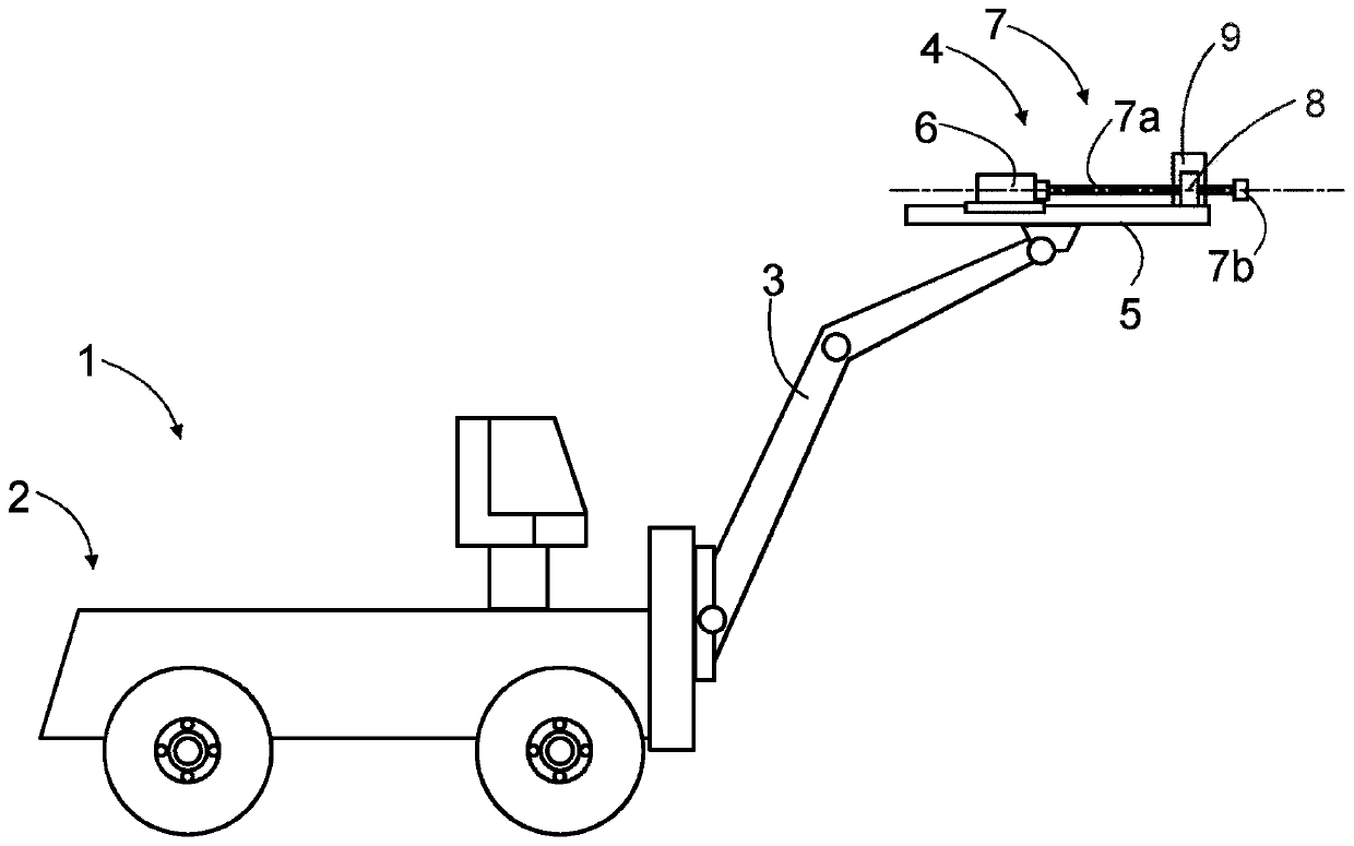
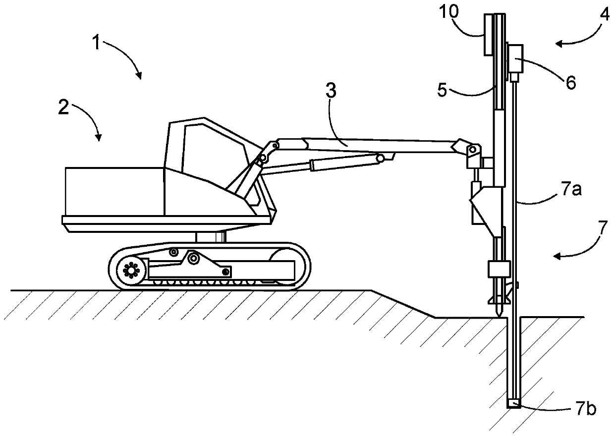
[0056] figure 1 A rock drilling rig 1 is shown as an example of a mining vehicle comprising a feed beam. Rock bolting rigs, charge rigs and survey vehicles may also include booms provided with feed beams. The improved feed beam disclosed in this patent application can be applied to all types of feed beams employed in mining operations.

[0057] The rock drilling rig 1 may comprise a movable transport carrier 2 and one or more booms 3 connected to the transport carrier 2 . At the distal portion of the boom 3 may be a drilling unit 4 . The drilling unit 4 may comprise a feed beam 5 and a rock drilling machine 6 supported on the feed beam 5 . The rock drilling machine 6 may comprise a drill shank at the front end of the rock drilling machine 6 for connecting the tool 7 . Furthermore, the drilling unit 4 may comprise one or more drill rod handling devices 8, such as tool holding devices, tool changing devices or robots, and tool magazines or tool stores. Besides, one or more ...


PUM


Abstract

The invention relates to a feed beam, a rock drilling unit and to a method of manufacturing a feed beam. The feed beam (5) comprises a basic profile element (11), which has two or more superimposed material layers (12, 13). At least one of the material layers may be made of composite material.

Description

technical field [0001] The invention relates to a feed beam of a rock drilling unit. The feed beam is an elongate piece that includes support surfaces for supporting and guiding the rock drilling machine. [0002] The invention also relates to a method of manufacturing a feed beam. [0003] The field of the invention is defined more particularly in the preambles of the independent claims. Background technique [0004] Different types of rock drilling equipment are used in mines and other workplaces. The rock drilling equipment is provided with one or more booms, and the rock drilling unit is arranged at the distal end of the booms. The rock drilling unit comprises a feed beam along which the rock drilling rig is configured to move during the drilling process. Modern feed beams are constructed from extruded aluminum profiles which are relatively strong and lightweight. However, current feed beams still appear to contain some disadvantages. Contents of the invention ...

Claims


Application Information

Patent Timeline
IPC IPC(8): E21B15/00E21B7/02
CPCE21B7/025E21B15/00B32B1/08B32B27/08B32B27/065B32B2597/00B32B5/18B32B2262/106B32B2266/0278B32B2307/56B32B27/40
Inventor 基莫·埃罗宁安西·许韦里宁保罗·布朗斯蒂芬·康纳利里斯托·卡利宁西尔帕·劳尼斯尤哈·皮波宁埃萨·兰塔拉泰穆·马扬德
Owner SANDVIK MINING & CONSTR OY
Features
  • R&D
  • Intellectual Property
  • Life Sciences
  • Materials
  • Tech Scout
  • Unparalleled Data Quality
  • Higher Quality Content
  • 60% Fewer Hallucinations
Learn More