Geotechnical cloth thickness measuring device

A geotextile and thickness measurement technology, which is applied in the direction of mechanical thickness measurement, etc., can solve the problems of lower detection accuracy and damage to the detector, and achieve the effects of accurate measurement accuracy, slow movement of the meter head, and reduced damage

Active Publication Date: 2019-06-28
北京铁城检测认证有限公司
View PDF9 Cites 3 Cited by
  • Summary
  • Abstract
  • Description
  • Claims
  • Application Information

AI Technical Summary

Problems solved by technology

[0005] The above existing technical solutions have the following defects: but when the geotextile needs to be replaced, the balance bar needs to be lifted. At this time, the balance bar will push the measuring end of the detector to move, which will easily cause damage to the detector and reduce the detection accuracy.

Method used


Image

  • Geotechnical cloth thickness measuring device
  • Geotechnical cloth thickness measuring device
  • Geotechnical cloth thickness measuring device

Examples


Embodiment 1

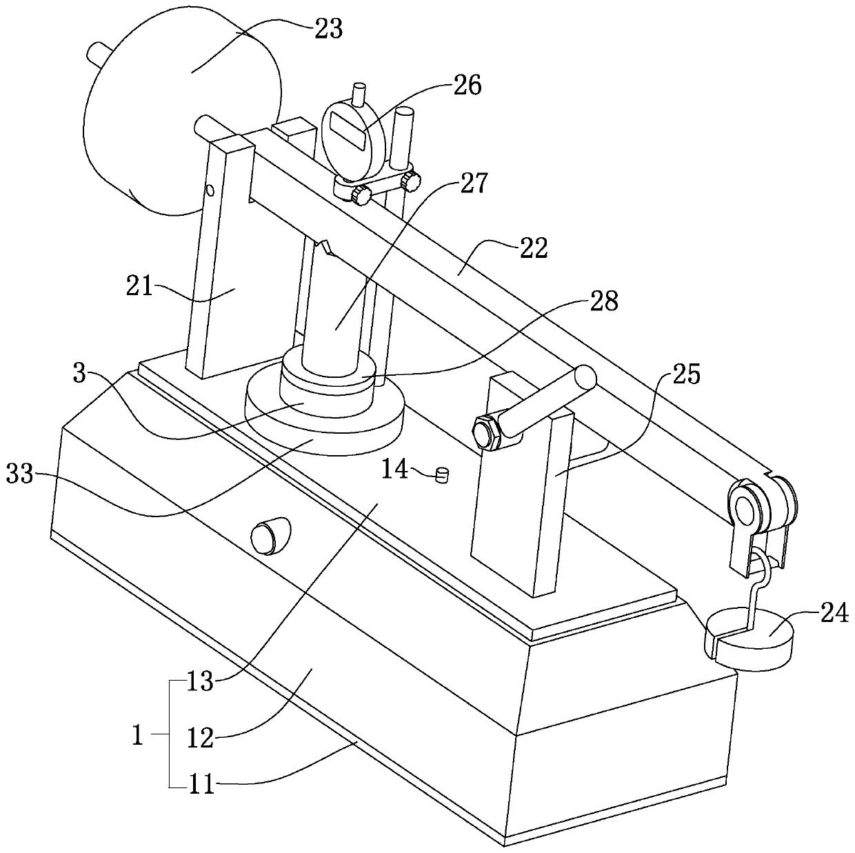
[0036] refer to figure 1 , discloses a geotextile thickness measuring device for the present invention, including a base 1, the base 1 includes a lower base plate 11, a side plate 12 and an upper base plate 13, the lower base plate 11 and the upper base plate 13 are steel plates with a square structure, and the side plates 12 are welded Between the upper bottom plate 13 and the lower bottom plate 11 , the base 1 is surrounded by a square-shaped housing.

[0037] refer tofigure 1 , The base 1 is provided with a measuring mechanism 2 . The measuring mechanism 2 comprises a vertical bar 27 welded on the surface of the upper base plate 13 facing away from the lower base plate 11. The vertical plate 21 is a square plate whose thickness direction is arranged along the length direction of the upper base plate 13. The vertical plate 21 is pierced with a hinge shaft, and the hinge shaft The axis is located in the horizontal plane, and the hinge shaft is covered with a pressure rod 22 ...

Embodiment 2

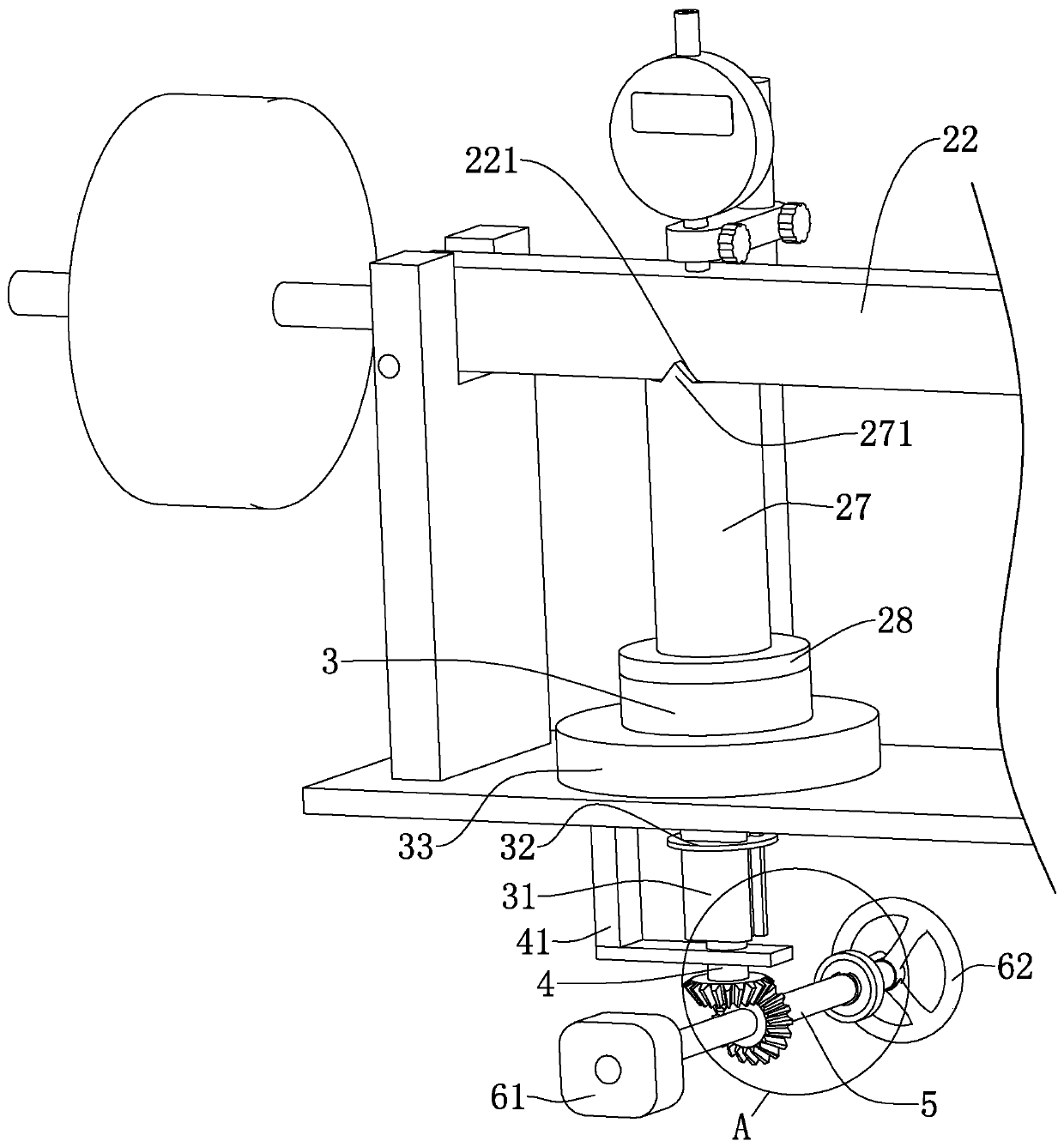
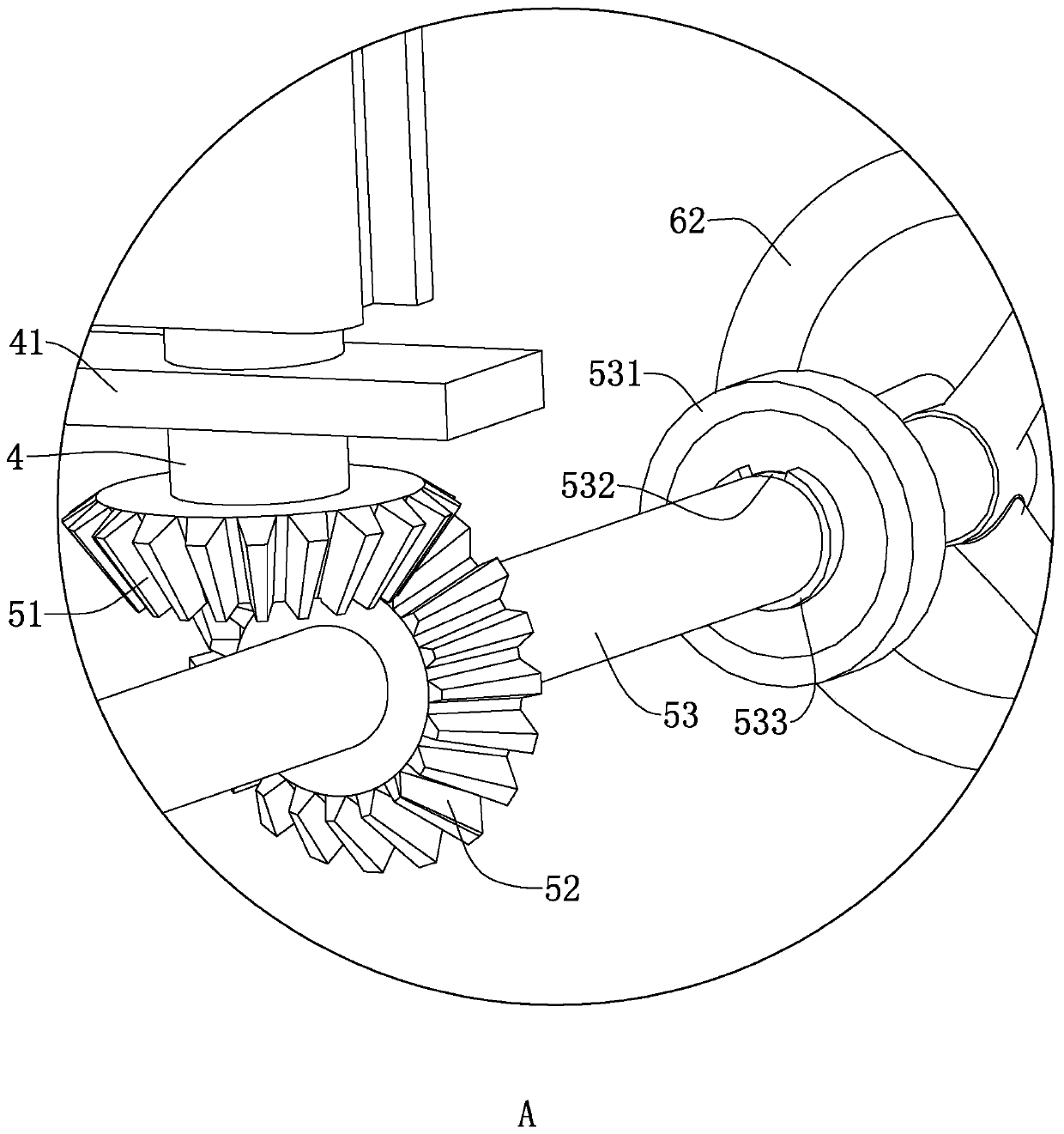
[0049] refer to Figure 5 , a geotextile thickness measuring device, the difference from Embodiment 1 is that the drive screw 4 is sleeved with a positioning ring 42 embedded in the lower bottom plate 11, the positioning ring 42 is rotationally connected with the drive screw 4, and the drive mechanism 5 It includes a worm wheel 54 that is sleeved on the outside of the drive screw 4 using a flat key. A worm 55 is meshed with the worm wheel 54. The worm 55 is rotationally connected with the base 1. One end of the worm 55 is connected to a drive motor 61 through a coupling, and the other end of the worm 55 is passed through The bolt compression connection is provided with a hand wheel 62 .

[0050] The implementation principle of the above-mentioned embodiment is:

[0051] The drive motor 61 drives the worm 55 to rotate, and the worm 55 drives the worm wheel 54 to rotate, so that the worm wheel 54 drives the drive screw 4 to rotate. The worm wheel 54 and the worm 55 have a good ...


PUM


Abstract

The invention discloses a geotechnical cloth thickness measuring device, which comprises a base. A vertical plate is fixed on the base; a pressing rod arranged horizontally is hinged to the vertical plate; and a pressure block is hinged at one end of the pressing rod. A support plate being abutted against the pressing rod is fixedly arranged on the base. A gauge is abutted against the upper surface of the pressing rod. An upper pressing ring is fixedly arranged at one end, facing the base, of the vertical rod; a lower pressing ring arranged on the base is abutted against the lower surface of the upper pressing ring; an adjusting tube is fixed on the surface, being opposite to the upper pressing ring, of the lower pressing ring; and at least one straight line is formed in the cross sectionof the adjusting tube. An avoidance hole that accommodates the adjusting tube and cooperates with an upper bottom plate is formed in the base. A limiting ring arranged in the inner cavity of the baseis fixedly arranged at the side of the adjusting tube; a driving screw is arranged at one end, extending into the base, of the adjusting tube in threaded connection; and the driving screw and the baseare in rotating connection; and a driving mechanism for driving the driving screw to rotate around the own axis is connected to the driving screw. Therefore, the damage on the gauge caused by liftingof the pressing rod is damaged and the measurement precision is improved.

Description

technical field [0001] The invention relates to the field of geotextile testing equipment, in particular to a geotextile thickness measuring equipment. Background technique [0002] Geotextile thickness gauge is an instrument used to test the thickness of geotextile synthetic materials under different pressures and specified pressure time. Due to the thin nature of geotextile synthetic materials, the accuracy requirements of its measuring instruments are compared high. [0003] The Chinese utility model patent with the authorized notification number CN208091415U discloses a geotextile thickness gauge, including a base, one end of the base is provided with a support seat, a balance bar is hinged on the support seat, and the left and right ends of the balance bar are respectively equipped with counterweights And the weight plate, there is a reference plate on the base close to the support seat, a presser foot is provided on the reference plate, the presser foot is located und...

Claims


Application Information

Patent Timeline
Patent Type & Authority Applications(China)
IPC IPC(8): G01B5/06
Inventor 高绍海
Owner 北京铁城检测认证有限公司
Why Eureka
Try Eureka