
Feed-through voltage compensation circuit unit, circuit and liquid crystal display device

A technology of a liquid crystal display device and a compensation circuit, which is applied to static indicators, instruments, etc., can solve problems affecting pixel charging, etc., and achieve the effects of increasing design costs, solving display problems, and improving display problems

Active Publication Date: 2019-06-28
XIANYANG CAIHONG OPTOELECTRONICS TECH CO LTD
View PDF4 Cites 1 Cited by
  • Summary
  • Abstract
  • Description
  • Claims
  • Application Information

AI Technical Summary

Problems solved by technology

[0005] This method can reduce the effect of △Vp, but it will affect the pixel charging

Method used


Image

  • Feed-through voltage compensation circuit unit, circuit and liquid crystal display device
  • Feed-through voltage compensation circuit unit, circuit and liquid crystal display device
  • Feed-through voltage compensation circuit unit, circuit and liquid crystal display device

Examples


Embodiment 1

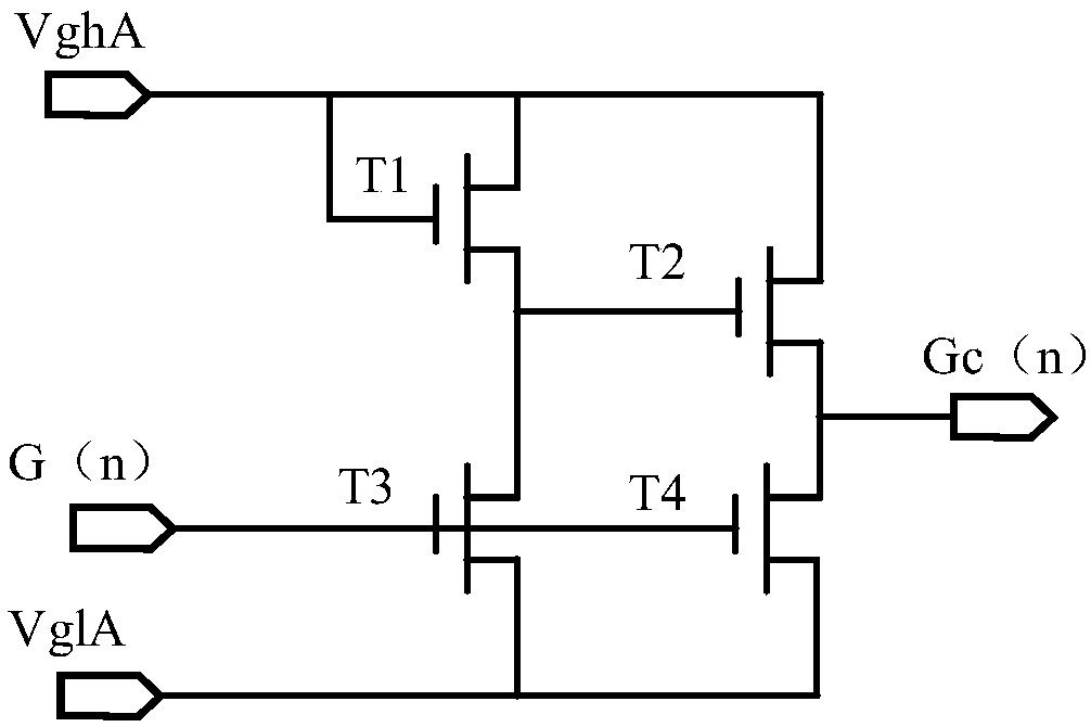
[0042] See image 3 , image 3 It is a Feedthrough voltage compensation circuit unit provided by an embodiment of the present invention. Specifically, the Feedthrough voltage compensation circuit unit may include: a first input terminal VghA, a second input terminal VglA, a third input terminal G(n), a first switching tube T1, a second switching tube T2, and a third switching tube T3 , The fourth switch tube T4 and the output terminal Gc(n); among them,

[0043] The first switch tube T1 and the third switch tube T3 are sequentially connected in series between the first input terminal VghA and the second input terminal VglA, and the control terminal of the first switch tube T1 is electrically connected To the first input terminal VghA, the control terminal of the third switch tube T3 is electrically connected to the third input terminal G(n);

[0044] The second switch tube T2 and the fourth switch tube T4 are sequentially connected in series between the first input terminal VghA a...

Embodiment 2

[0051] See Figure 4 to Figure 13 And see again image 3 , Figure 4 Is an output waveform diagram of a Feedthrough voltage compensation circuit unit provided by an embodiment of the present invention; Figure 5 It is an equivalent circuit diagram of a Feedthrough compensation pixel provided by an embodiment of the present invention; Image 6 It is a schematic diagram of a layout setting of a pixel unit in 4Domain VA Mode according to an embodiment of the present invention; Figure 7 It is another schematic diagram of pixel unit layout setting in 4Domain VA Mode provided by an embodiment of the present invention; Figure 8 It is an equivalent circuit diagram of a pixel in 4Domain VA Mode provided by an embodiment of the present invention; Picture 9 It is a schematic diagram of pixel unit layout setting in 8Domain VA Mode provided by an embodiment of the present invention; Picture 10 It is a pixel equivalent circuit diagram in 8DomainVA Mode provided by an embodiment of the prese...

Embodiment 3

[0071] See Figure 14 and Figure 15 , Figure 14 This is a Feedthrough voltage compensation circuit provided by an embodiment of the present invention, Figure 15 It is a schematic structural diagram of a liquid crystal display device provided by an embodiment of the present invention. This embodiment describes in detail the Feedthrough voltage compensation circuit provided by the present invention and the liquid crystal display device using the Feedthrough voltage compensation circuit on the basis of the above embodiments.

[0072] Specifically, the Feedthrough voltage compensation circuit includes N Feedthrough voltage compensation circuit units, and each Feedthrough voltage compensation circuit unit corresponds to a scan driving circuit unit. Wherein, the first input terminal of each Feedthrough voltage compensation circuit unit is connected to form the first input terminal VghB of the Feedthrough voltage compensation circuit, that is, the first input terminal Vgh1A of the fir...


PUM


Abstract

The invention relates to a feed-through voltage compensation circuit unit, a circuit and a liquid crystal display device. The compensation circuit unit comprises a first input end Vgh A, a second input end VglA, a third input end G (n), a first switch tube T1, a second switch tube T2, a third switch tube T3, a fourth switch tube T4 and an output end Gc (n). The first switch tube T1 and the third switch tube T3 are sequentially connected in series between the first input end Vgh A and the second input end VglA. The second switch tube T2 and the fourth switch tube T4 are sequentially connected in series between the first input end Vgh A and the second input end VglA. And the output end Gc (n) is electrically connected to a node formed by connecting the second switch tube T2 and the fourth switch tube T4 in series. By providing the compensation circuit unit, the influence of the Fedthauge voltage on the panel pixel voltage is reduced, the circuit is simple and easy to implement, the design cost is reduced, and the production efficiency is improved.

Description

Technical field [0001] The present invention relates to the technical field of liquid crystal display, in particular to a feedthrough voltage compensation circuit unit, a circuit and a liquid crystal display device. Background technique [0002] Liquid Crystal Display (LCD) is a type of flat panel display, which is widely used in TVs, computers, smart phones, mobile phones, car navigation devices, e-books and other products. Liquid crystal display devices have the advantages of low power consumption, small size, and low radiation, gradually replacing cathode ray tube (Cathode Ray Tube, CRT) display devices. [0003] During the driving process of the liquid crystal display device, the scanning line loads the scanning voltage into the pixels of each row. The pixels are affected by the voltage change of the scanning signal when the charging is completed. When the scanning voltage changes from a high level to a low level, the pixel voltage Due to the presence of the Feedthrough voltag...

Claims


Application Information

Patent Timeline
IPC IPC(8): G09G3/36
Inventor 吴永良
Owner XIANYANG CAIHONG OPTOELECTRONICS TECH CO LTD
Features
  • Generate Ideas
  • Intellectual Property
  • Life Sciences
  • Materials
  • Tech Scout
  • Unparalleled Data Quality
  • Higher Quality Content
  • 60% Fewer Hallucinations
Learn More