
Display panel and display device

A display panel and display area technology, which is applied in the direction of semiconductor devices, electrical components, circuits, etc., can solve the problems that the optical sensor cannot sense normally and the light transmittance is low, and achieve the effect of improving the light transmittance and reducing the blocking effect

Active Publication Date: 2019-06-28
BOE TECH GRP CO LTD +1
View PDF5 Cites 24 Cited by
  • Summary
  • Abstract
  • Description
  • Claims
  • Application Information

AI Technical Summary

Problems solved by technology

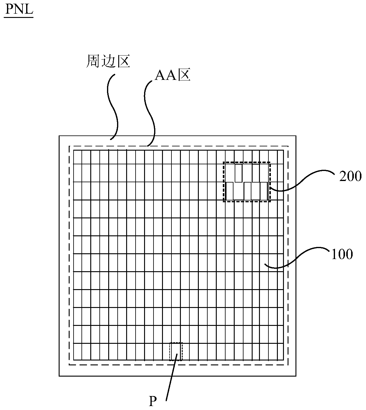
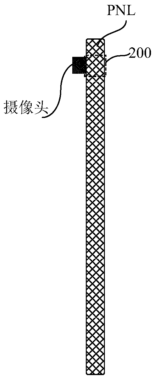
[0003] Embodiments of the present invention provide a display panel and a display device, which can solve the problem that the optical sensor cannot sense normally due to low light transmittance at the position corresponding to the optical sensor in the display panel

Method used


Image

  • Display panel and display device
  • Display panel and display device
  • Display panel and display device

Examples


Embodiment Construction

[0029] The following will clearly and completely describe the technical solutions in the embodiments of the present invention with reference to the accompanying drawings in the embodiments of the present invention. Obviously, the described embodiments are only some, not all, embodiments of the present invention. Based on the embodiments of the present invention, all other embodiments obtained by persons of ordinary skill in the art without making creative efforts belong to the protection scope of the present invention.

[0030] Unless otherwise defined, the technical terms or scientific terms used in the embodiments of the present invention shall have the usual meanings understood by those skilled in the art to which the present invention belongs. "First", "second" and similar words used in the embodiments of the present invention do not indicate any order, quantity or importance, but are only used to distinguish different components. "Comprising" or "comprising" and similar w...


PUM


Abstract

The embodiment of the invention provides a display panel and a display device, relates to the technical field of display, and can solve the problem that an optical sensor cannot perform sensing due tolow light transmittance at the position, corresponding to the optical sensor, in the display panel. In the display panel, a pixel region comprises a first pixel group and a second pixel group which are continuous in the row direction and the column direction and are periodically arranged; each of the first pixel group and the second pixel group comprises at least two sub-pixels which are continuously arranged in the row direction and have different colors; a light-transmitting area comprises third pixel groups which are arranged at intervals in the row direction and the column direction; eachof the third pixel groups comprises at least three sub-pixels which are arranged in the row direction and have different colors; the difference value between the row number of any sub-pixel in the third pixel group and the row number of any sub-pixel in the pixel region, which is located in the same column as the sub-pixel and has the same color as the sub-pixel, is an integral multiple of M, wherein M is the difference value of the row numbers of every two adjacent sub-pixels of the color in the pixel area in the column direction.

Description

technical field [0001] The present invention relates to the field of display technology, in particular to a display panel and a display device. Background technique [0002] With the development of high-resolution display screens, terminal display products are developing towards smaller and smaller appearance frames (such as full-screen displays), and the sensing devices that need to be mounted (such as infrared sensors, etc.) will occupy most of the frame . To solve this contradiction, a more effective solution is to place the sensing device on the back of the display; however, due to the high density of traces in the display, the transmittance of the display when the sensing device is set is small, which will hinder Normal sensing of sensing device. Contents of the invention [0003] Embodiments of the present invention provide a display panel and a display device, which can solve the problem that the optical sensor cannot sense normally due to low light transmittance ...

Claims


Application Information

Patent Timeline
Patent Type & Authority Applications(China)
IPC IPC(8): H01L27/32
CPCH10K59/352H10K59/353
Inventor 韩林宏吴建鹏张毅孙阔
Owner BOE TECH GRP CO LTD
Learn More