A battery pack for electric forklift

A technology for electric forklifts and battery packs, applied to secondary batteries, battery pack components, circuits, etc., can solve problems such as low heat dissipation efficiency, and achieve high heat dissipation efficiency, reasonable structure, and stable performance

Active Publication Date: 2020-09-29
SHENZHEN LOTUT INNOVATION DESIGN CO LTD
View PDF6 Cites 0 Cited by
  • Summary
  • Abstract
  • Description
  • Claims
  • Application Information

AI Technical Summary

Problems solved by technology

[0005] The purpose of the present invention is to provide a battery pack for electric forklifts in view of the deficiencies of the prior art. By driving the directional compression part to actively dissipate the hot air from the chassis; during the reset process of the compression part, the chassis External air is adsorbed into the chassis to realize rapid airflow conversion before and after the battery load, and solve the problem of low heat dissipation efficiency in the battery load state existing in the prior art

Method used


Image

  • A battery pack for electric forklift
  • A battery pack for electric forklift
  • A battery pack for electric forklift

Examples


Embodiment 1

[0029] Embodiments of the present invention are described in detail below, examples of which are shown in the drawings, wherein the same or similar reference numerals designate the same or similar elements or elements having the same or similar functions throughout. The embodiments described below by referring to the figures are exemplary and are intended to explain the present invention and should not be construed as limiting the present invention.

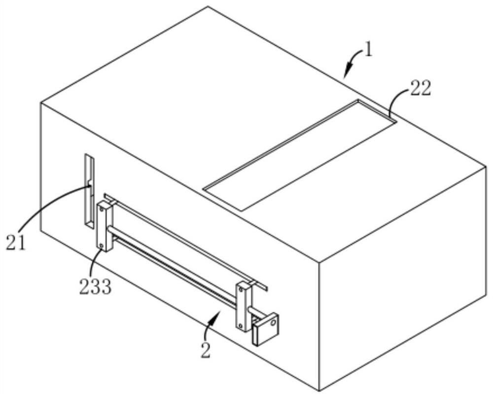
[0030] like Figures 1 to 4 As shown, a battery pack for an electric forklift, including a chassis 1, also includes:

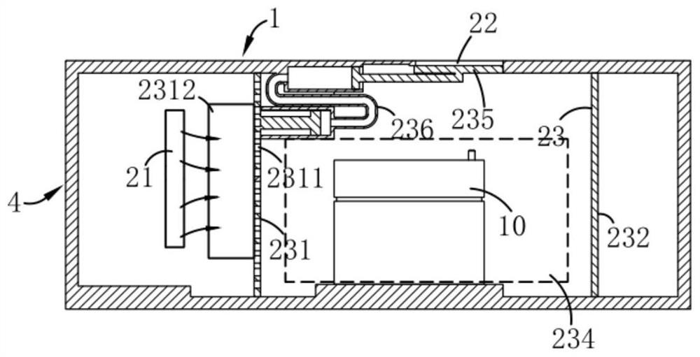
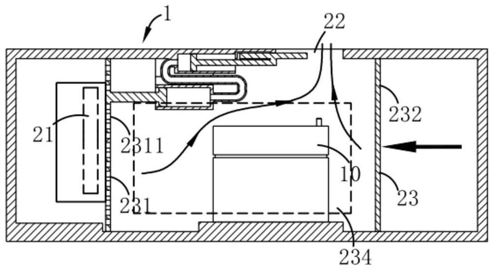
[0031] The heat dissipation mechanism 2 is used to cool the battery 10 in the case 1. The heat dissipation mechanism 2 includes an air intake passage 21, an air outlet passage 22 and a compression assembly 23 opened in the case 1. The air intake Both the passage 21 and the air outlet passage 22 are opened on the chassis 1 and communicate with the outside; Dust removal process is carried out, the compression par...

Embodiment 2

[0034] like figure 1 , 5 , 6 and 7, wherein the same or corresponding parts as in the first embodiment adopt the corresponding reference numerals with the first embodiment, for the sake of simplicity, only the differences from the first embodiment are described below; the second embodiment is similar to the first embodiment The difference of Example 1 is that the compression assembly 23 also includes a transmission part 233 connecting the compression part 232 and the filter part 231, and the transmission part 233 includes a connection block A2331, a connection block B2332, a connecting rod 2333, and a return spring 2334 And the push plate 2335, the connection block A2331 and the connection block B2332 are fixedly connected with the filter part 231 and the compression part 232 respectively and are located outside the chassis 1, the connecting rod 2333 is fixed horizontally on the connection block B2332 and Slidingly connected with the connecting block A2331, the return spring ...


PUM


Abstract

The invention relates to the technical field of forklift production and particularly relates to a battery pack for an electric forklift. The battery pack comprises a chassis and a heat dissipating mechanism. The heat dissipating mechanism comprises an air inlet passage, an air outlet passage and a compression assembly arranged in the chassis, and both the air inlet passage and the air outlet passage are arranged in the chassis and communicate with the outside. The compression assembly includes a filtering portion and a compression portion, the filtering portion is used for performing dust removal processing on airflow entering through the air inlet passage, the compression portion is used for discharging air in the chassis, the compression portion is in transmission connection with the filtering portion, and the compression portion drives the filtering portion to close the air inlet passage and the air outlet passage is opened at the same time. The compression portion is driven in a directed direction to discharge hot air flow out of the chassis in an active heat radiation way, the air outside the chassis is sucked into the chassis in the reset process of the compression portion torealize rapid airflow conversion before and after a storage battery is loaded, and the problem of low dissipation efficiency of the storage battery in a loaded state in the prior art is solved.

Description

technical field [0001] The invention relates to the technical field of forklift production, in particular to a battery pack used for an electric forklift. Background technique [0002] At present, in the field of electric forklifts, batteries are mostly placed in battery packs with air holes to dissipate heat during battery use; conventional electric forklifts have a small rated load and are mostly used in low-strength working conditions. Due to the limitation of the use site and working conditions, the protection level of the battery box of the electric forklift is low, and the natural cooling method is generally adopted. The heat dissipation efficiency is low, and the heat cannot be discharged in time, which affects the service life and performance of the corresponding components. Work requirements. With the emergence of large-tonnage electric forklifts and high-intensity operating conditions, battery capacity is also gradually increasing, so it puts forward higher requir...

Claims


Application Information

Patent Timeline
Patent Type & Authority Patents(China)
IPC IPC(8): H01M10/613H01M10/625H01M10/6556H01M10/6564H01M2/10
CPCY02E60/10
Inventor 祝守新
Owner SHENZHEN LOTUT INNOVATION DESIGN CO LTD
Why Eureka
Try Eureka