Safe and rapid electric pole climbing tool

A utility pole and fast technology, applied in climbing, sports accessories, etc., can solve problems such as insecurity, time-consuming and labor-intensive, and achieve the effect of high safety performance

Active Publication Date: 2019-07-02
GUANGDONG POWER GRID CORP ZHAOQING POWER SUPPLY BUREAU
16 Cites 9 Cited by

AI-Extracted Technical Summary

Problems solved by technology

The wires on the utility poles need to be repaired by electricians. Because the utility poles are tall and cylindrical, in most cases, electricians ...

Method used

[0040] The detachable gear 2 is also equivalent to surrounding the two semicircle-shaped plates 1 except for transmission,...

Abstract

The invention discloses a safe and rapid electric pole climbing tool, which comprises a position limiting sliding device, wherein the position limiting sliding device comprises a round pipe formed bytwo semi-circular arc-shaped plates of the same shape; a dismountable gear is rotationally arranged on the outer wall of the round pipe; the two semi-circular arc-shaped plates are connected and fixedthrough screw bolts and sleeve an electric pole; a driving device is arranged on the outer side wall of one semi-circular arc-shaped plate; a climbing device is arranged on the outer side wall of theother semi-circular arc-shaped plate, and comprises a lifting frame,and telescopic rods are arranged in a vertical plate of the lifting frame; a support foot plate is connected with the bottom end ofeach of the telescopic rods. The safe and rapid electric pole climbing tool has the advantages that the safe and rapid electric pole climbing tool can be arranged on the electric poles with differentsizes and diameters; through the transmission between a motor and a plurality of gears, the ascending and descending can be realized; the time and the labor are saved; through the use of the screw bolts for limiting the safe and rapid electric pole climbing tool onto the electric pole, the safe and rapid electric pole climbing tool is also provided with a dismountable gear with the locking function; the transmission is realized; the whole device can be protected from being separated,and the safety performance is high.

Application Domain

Climbing

Technology Topic

Image

  • Safe and rapid electric pole climbing tool
  • Safe and rapid electric pole climbing tool
  • Safe and rapid electric pole climbing tool

Examples

  • Experimental program(1)

Example Embodiment

[0025] The following will clearly and completely describe the technical solutions in the embodiments of the present invention with reference to the accompanying drawings in the embodiments of the present invention. Obviously, the described embodiments are only a part of the embodiments of the present invention, not all the embodiments, based on The embodiments of the present invention, and all other embodiments obtained by those of ordinary skill in the art without creative work, fall within the protection scope of the present invention.
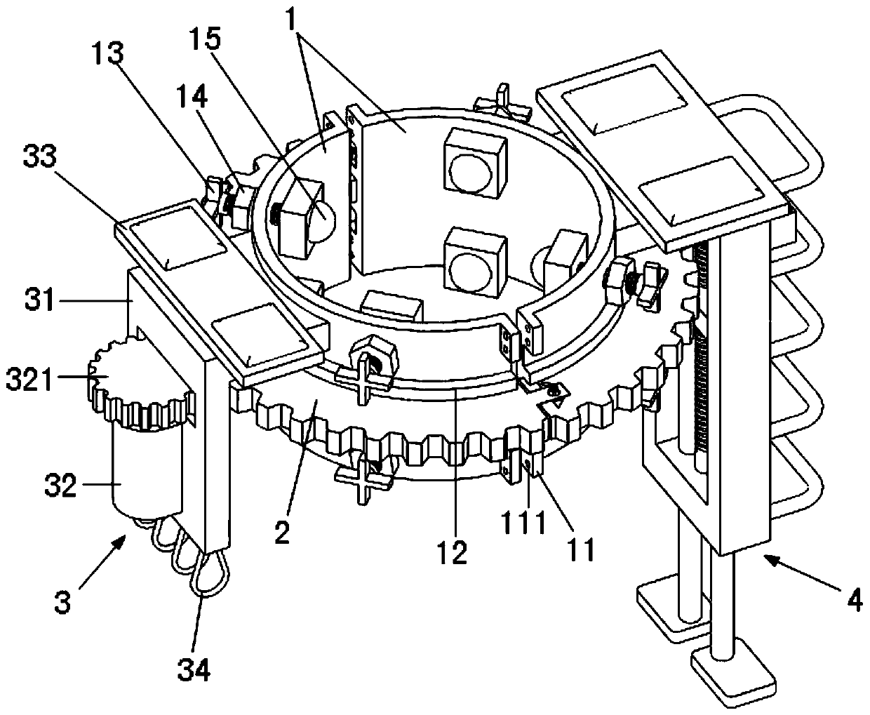
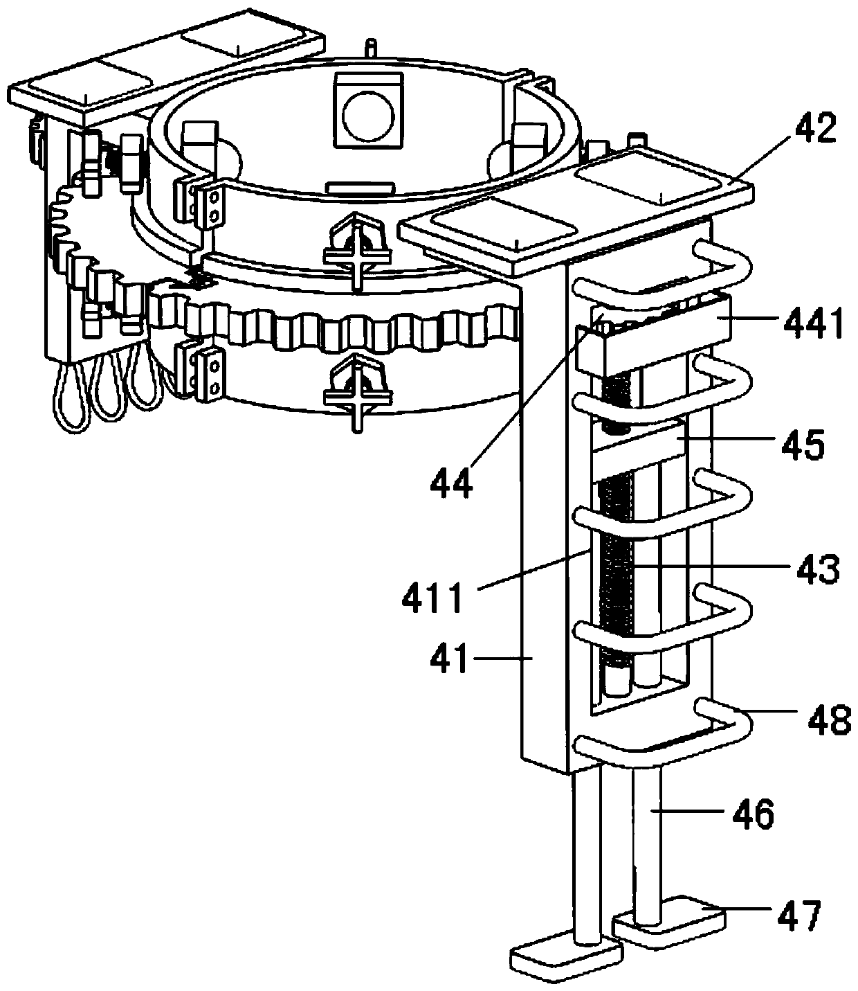
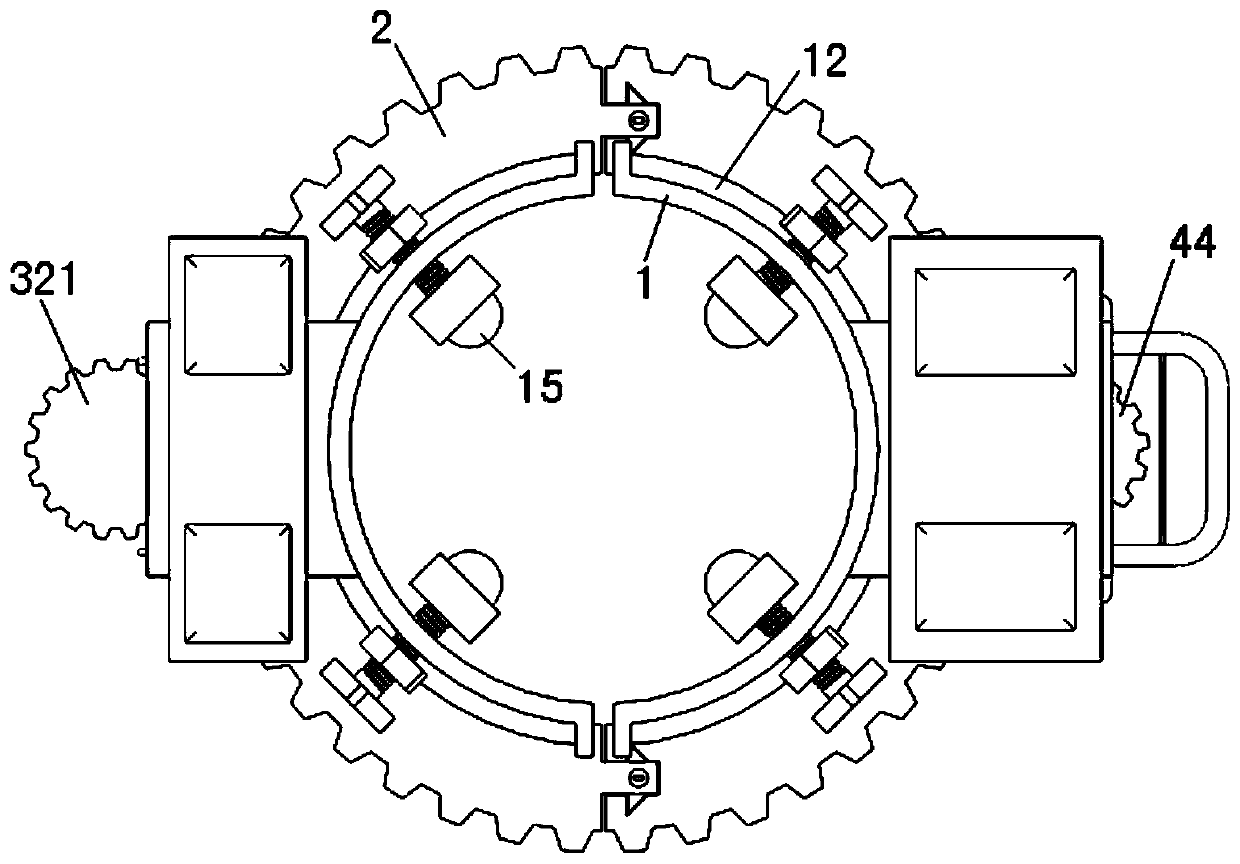
[0026] by Figure 1 to Figure 6 As shown, a safe and quick utility pole climbing tool includes a limit sliding device. The limit sliding device includes a circular tube composed of two semicircular arc-shaped plates 1 of the same shape, and the outer wall of the circular tube rotates A detachable gear 2 is provided. Two semi-circular arc-shaped plates 1 are connected and fixed by bolts and sleeved on the electric pole. One of the semi-circular arc-shaped plates 1 is provided with a driving device 3 on the outer side wall, and the other semi-circular arc-shaped plate 1 Climbing device 4 is provided on the outer side wall of.
[0027] Furthermore, the left and right ends of the semicircular arc-shaped plate 1 respectively have a pair of connecting ears 11 distributed up and down and extending radially outward, and the connecting ears 11 are provided with a plurality of bolt connecting holes 111.
[0028] Furthermore, the center of the outer surface of the semicircular arc-shaped plate 1 is formed with a pair of limiting edges 12 distributed up and down and extending radially outward, and the detachable gear 2 is rotatably arranged between the two limiting edges 12.
[0029] Furthermore, the upper and lower ends of the wall of the semi-circular arc plate 1 are respectively screwed with a plurality of cross-shaped adjusting bolts 13, which pass through the wall of the semi-circular arc plate 1 and are fixed with a universal ball. 15. A lock nut 14 is screwed on the cross-shaped adjusting bolt 13.
[0030] Furthermore, the driving device 3 includes a mounting frame 31 fixed on the outer wall of the semicircular arc-shaped plate 1, the mounting frame 31 is bent downwards and the top surface of the mounting frame 31 is provided with a first footrest 33. A drive motor 32 is fixed on the outer surface of the vertical plate of the mounting frame 31, and a drive gear 321 is provided on the output shaft of the drive motor 32. The drive gear 321 passes through the through slot provided on the vertical plate of the mounting frame 31 and is in contact with The detachable gear 2 meshes.
[0031] Furthermore, the climbing device 4 includes a lifting frame 41 fixed on the outer wall of the semi-circular arc-shaped plate 1, the lifting frame 41 is bent downward and the top surface of the lifting frame 41 is provided with a second footrest 42, The center of the vertical plate of the lifting frame 41 is provided with a lifting through groove 411, the screw rod 43 is rotatably connected to the upper and lower ends of the lifting through groove 411, and the upper end of the screw rod 43 is fixed with an adjustment for meshing with the detachable gear 2 The gear 44, the lifting block 45 is screwed to the screw rod 43, a pair of telescopic rods 46 are fixed at both ends of the bottom surface of the lifting block 45, and the bottom end of the telescopic rod 46 passes downward through the lower end surface of the lifting channel 411 and the lifting frame The wall between the bottom surfaces of the vertical plates 41 is connected with a supporting foot plate 47.
[0032] Furthermore, the detachable gear 2 includes a semicircular male gear 21 and a semicircular female gear 22. The front surfaces of both ends of the semicircular male gear 21 have protrusions 211 extending forwardly. There is a lock 23. The front surfaces of both ends of the semicircular female gear 22 are provided with connecting grooves 221 that cooperate with the protrusions 211; the lock 23 includes a pair of symmetrical stoppers with inclined outer side walls. Block 231, two stop blocks 231 are slidably arranged in the sliding through grooves 2111 provided in the protrusion 211, and a pair of triangular grooves 222 are provided on the left and right sides of the connecting groove 221 to cooperate with the stop blocks 231 , The protrusion 211 is inserted in the connecting groove 221, a plurality of return springs 232 are connected between the front and rear ends of the opposite surfaces of the two stop blocks 231, and the centers of the opposite surfaces of the two stop blocks 231 are respectively provided with There is a slot 2311, the bottom of the protrusion 211 is inserted with a rotating rod 233, the rotating rod 233 is located between the two slots 2311, the top surface of the protrusion 211 is provided with a rotating circular groove 2112, a rotating circular groove 2112 Connecting with the sliding through groove 2111, the upper end of the rotating rod 233 is respectively provided with a spreading plate 234 and a twisting plate 235 from bottom to top.
[0033] Furthermore, a plurality of safety buckles 34 are provided on the bottom surface of the vertical plate of the mounting frame 31.
[0034] Furthermore, a safety baffle 441 is fixed on the outer side wall of the vertical plate of the lifting frame 41 and facing the adjustment gear 44.
[0035] Furthermore, a plurality of evenly distributed stepping rods 48 are fixed on the outer side wall of the vertical plate of the lifting frame 41.
[0036] The working principle of the present invention:
[0037] 1. First wrap the two semicircular arc-shaped plates 1 on the telegraph pole and connect them with bolts to form a complete circular sleeve, and then twist the cross-shaped adjusting bolt 13 to make all the universal balls 15 abut on the telegraph pole , And locked and fixed by the lock nut 14, at this time the whole device can slide up and down on the pole;
[0038] 2. The semicircular male gear 21 and the semicircular female gear 22 are matched between the two limit edges 12 to form a complete gear, and the protrusion 211 in the semicircular male gear 21 is inserted into the semicircular female gear 22 In the connecting groove 221 in the middle, and then twist the twisting plate 235, first rotate the spreading plate 234 to a position parallel to the opposite surface of the stopper 231, and then insert the spreading plate 234 downward into the two stoppers 231 And then rotate again, the support plate 234 pushes the two stoppers 231 outwards. At this time, the two stoppers 231 slide toward each other and are locked in the triangular groove 222, while the support plate 234 is stuck in the slot In 2311, the assembly of the detachable gear 2 is prevented, but when it needs to be disassembled, the spreading plate 234 can be pulled out from the two slots 2311 by pulling the twisting plate 235 upward, and the stopper 231 is reset again. Complete disassembly;
[0039] 3. Through the operation of the drive motor 32, the detachable gear 2 can be rotated, thereby driving the adjustment gear 44 to rotate, and the screw 43 will rotate the lifting block 45 to lift, and finally realize the lifting of the telescopic rod 46. The electrician can rely on Lifting and lowering on the stepping rod 48 is quick and safe.
[0040] In addition to being capable of transmission, the detachable gear 2 is equivalent to enclosing the two semi-circular arc-shaped plates 1 so that the connection between the two semi-circular arc-shaped plates 1 is stronger and the safety performance is higher.

PUM

no PUM

Description & Claims & Application Information

We can also present the details of the Description, Claims and Application information to help users get a comprehensive understanding of the technical details of the patent, such as background art, summary of invention, brief description of drawings, description of embodiments, and other original content. On the other hand, users can also determine the specific scope of protection of the technology through the list of claims; as well as understand the changes in the life cycle of the technology with the presentation of the patent timeline. Login to view more.

Similar technology patents

One-time password authentication method

Owner:SICHUAN CHANGHONG ELECTRIC CO LTD

Classification and recommendation of technical efficacy words

Why Eureka
Try Eureka